
Related Manuals for De Nora Capital Controls CHLORALERT 17CA3000 Series

Summary of Contents for De Nora Capital Controls CHLORALERT 17CA3000 Series
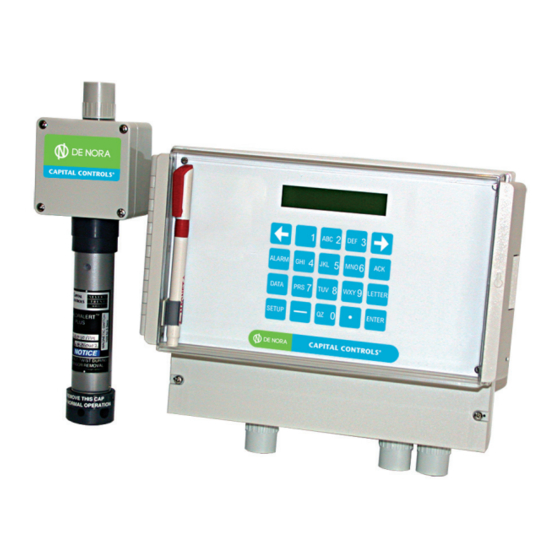
- Page 1 Instruction Manual Series 17CA3000 Chloralert Plus Multi-Gas Detector CAPITAL CONTROLS ® - 1 - 325.6610.17...
- Page 2 De Nora Water Technologies, Inc. reserves the rights to make engineering refinements that may not be described herein. It is the responsibility of the installer to contact De Nora Water Technologies, Inc. for information that cannot be answered specifically by these instructions.
-
Page 3: Table Of Contents
TABLE OF CONTENTS SAFETY SUMMARY ..............................7 READ FIRST ................................8 INTRODUCTION ...............................9 1.1 General ............................... 9 1.2 Model Number Breakdown ........................10 1.3 Specifications ............................11 INSTALLATION ..............................13 2.1 Inspection ..............................13 2.2 Location and Mounting ..........................13 2.3 Receiver Electrical Connections ....................... 13 2.4 Sensor/Transmitter Electrical Connections .................... - Page 4 4.3.1 Data Entry ............................ 38 4.3.2 Configuration ..........................38 4.3.3 Setup ............................39 4.3.3.1 Menu Navigation & Defaults ....................39 4.3.3.2 Select Sensor Channel ......................41 4.3.3.3 Select Sensor Type ........................ 41 4.3.3.4 Enter Sensor Calibration Parameters ..................41 4.3.3.5 Configure Alarm ........................42 4.3.3.6 Configure Digital Output ......................
- Page 5 4.4.2.4.4 Datalink Enable ......................61 4.4.2.4.5 Datalink Protocol ......................61 4.4.3 Run Calibration ........................61 4.4.4 Stop Calibration ........................62 CALIBRATION ........................... 63 Sensor Calibration ..........................63 5.1.1 Setup ..........................63 5.1.2 Source ..........................63 5.1.3 Calibration ..........................63 5.1.3.1 General Calibration Overview ..................63 5.1.3.2 ZERO Calibration Procedure ....................
- Page 6 LIST OF TABLES Table 2-1 Sensor Wiring and Configuration ......................17 Table 3-1 Gas Cross-Sensitivity Data ........................20 Table 4-1 Factory Default Database Parameters ....................40 Table 6-1 System Prompts (Datalink) ........................70 Table 6-2 Datalink Protocol ..........................71 Table 6-3 Datapoint Types ...........................
-
Page 7: Safety Summary
SAFETY SUMMARY GENERAL RETURN OF EQUIPMENT WARNINGS All equipment being returned to De Nora Water Technologies for repair must be free of any hazardous materials. Contact De Nora Water Technologies for authorization prior to returning equipment. INSTRUCTION MANUALS Do not install, maintain or operate this equipment without reading, understanding and following the proper De Nora Water Technologies instructions and manuals, other wise injury or damage may result. -
Page 8: Read First
De Nora Water Technologies instructions and manuals, otherwise injury or damage may result. RETURN OF EQUIPMENT All equipment being returned to De Nora Water Technologies for repair must be free of any hazardous materials. Contact De Nora Water Technologies for authorization prior to returning equipment. -
Page 9: Introduction
1.0 INTRODUCTION General The Chloralert™ Plus multifunction gas-leak detector is designed to be used for the detection and monitoring of Chlorine (Cl ) and Sulfur Dioxide (SO ) in ambient air. It also activates audio and visual alarms in the event that the concentration of these gases exceeds programmable preset levels. -
Page 10: Model Number Breakdown
Model Number Breakdown The following table shows the individual fields of the instrument’s model number and the selections available for each. Refer to the receiver’s data tag (shown below) for the specific model number configuration of the instrument. 17CA3 Enclosure Standard Wall Mounting Standard With key Locked door Analog Outputs... -
Page 11: Specifications
Specifications SYSTEM: Gases Chlorine Sulfur Dioxide Channels/Gases 4 max., channels and gas interchangeable for each receiver Gas Conc. Ranges Chlorine: 0-5, 0-10, 0-50 ppm Sulfur Dioxide: 0-10, 0-20, 0-100 ppm Ambient Temperature Receiver: -5 to +55°C (23 to 131°F) Sensor: -30 to +55°C (-22 to 131°F) Ambient Pressure: 0.8 to 1.2 atmospheres AC POWER:... - Page 12 Max. Distance Receiver to Sensor/Transmitter: 1000 ft. Wires (Xmttr/Receiver) Sample Draw None Sensor Check Optional Housing Sensor/Transmitter: Dimensions: 3.2 in.(W) x 11.0 in.(H)* x 2.2 in.(D) *12.6 in.(H) with gas-generator Weight: 1 lb. Materials: Electronic Housing Tube-PVC Junction Box-polycarbonate Receiver: Dimensions: 10.9 in.(W) x 8.6 in.(H) x 5.3 in.(D) Weight:...
-
Page 13: Installation
If the equipment is damaged to the extent that faulty operation may result, contact De Nora Water Technologies before installation. Always reference the complete instrument serial number and model number in all correspondence concerning the equipment supplied. -
Page 14: Figure 2-1 Receiver Outline Dimensions
325.6610.17 - 14 -... -
Page 15: Figure 2-2 Sensor/Transmitter Outline Dimensions
- 15 - 325.6610.17... -
Page 16: Figure 2-3 Interconnection Diagram
325.6610.17 - 16 -... -
Page 17: Sensor/Transmitter Electrical Connections
Sensor/Transmitter Electrical Connections WARNING ELECTRICAL SHOCK HAZARD. Equipment powered by AC line voltage presents a potential electrical shock hazard to the user. Make certain that the system input and digital output relay connections are disconnected from the operating branch circuit branch circuit before attempting to connect sensors to the receiver. -
Page 18: Figure 2-4 Sensor Wiring
Figure 2-4 Sensor Wiring 325.6610.17 - 18 -... -
Page 19: Functional Description
3.0 FUNCTIONAL DESCRIPTION General The 17CA3000 Chloralert Plus normally consists of two distinct elements, the sensor/transmitter and the receiver. The sensor/transmitter is located near potential sources of gas leaks or emissions while the receiver is located remotely in a control room, although in some instances, they may both be located at the same site. Both elements of the device have inputs and outputs. -
Page 20: Outputs
3.2.1.3 Outputs The output of the sensor/transmitter is wired directly to a terminal block in the receiver so care should be taken that the sensor is correctly connected to the receiver (refer to section 2.4). If the sensor/transmitter is connected incorrectly, no damage will occur but the LED indicator on the sensor/transmitter will not light and the LCD display on the receiver will indicate “BAD ID”. -
Page 21: Receiver Outputs
3.2.2.3 Receiver Outputs The outputs of the receiver fall into two categories • Analog - gas concentration data as a linear current output • Digital - relay contact-closure 3.2.2.3.1 Analog Outputs (AO) An optional 4-20 mA or 0-20 mA analog output linearly proportional to sensed gas concentration is available on terminal block TB1 for each sensor channel. -
Page 22: Operating Modes
ALARM DATA LETTER SETUP ENTER Figure 3-1 Chloralert™ Plus Keypad 3.2.2.5 Operating Modes The following four modes of operation may be selected: • RUN - displays concentration data • SETUP - setup menu • ALARMS - active alarm/events queue • DATA - historical alarm/events queue When the power is first applied, the unit activates in the RUN mode. -
Page 23: Display Modes
3.2.2.7 Display Modes The receiver has a 2 line, 20 character per line LCD display with a character height of 0.19 in. (4.86 mm). The display mode may be selected as either AUTO or MANUAL using the CONFIGURATION menu in the SETUP mode. If an alarm occurs with the display in either mode, the display will change to the 4-channel summary mode automatically. -
Page 24: Watchdog Timer Circuit
3.2.2.8 Watchdog Timer Circuit The “watchdog” circuit is intended to let the operator know that the microprocessor has stopped running. The circuit requires a constant input pulse from the microprocessor that only occurs during proper operation. If the input pulses stop for more than a second, the watchdog circuit will disable all of the relays and cause the display backlight to flash. -
Page 25: Self-Test Failure Messages
initializing the self-test procedure. It is an 8-digit code, with each digit being either 1 or 0, depending on whether an option is present or not. The positions of the digits to be entered correspond to the options below: RS232/ Ext. -
Page 26: Sensor Check
The REPEAT mode continues to cycle through the SELF-TEST sequence until terminated by the operator. When in REPEAT mode, the DISPLAY and KEYPAD self-tests are only performed during the first cycle and are skipped thereafter. In REPEAT mode, the display indicates the number of successful passes through the self-test cycle. If an error occurs while in REPEAT mode, the self-test will stop and the display will flash and indicate the nature of the error and the cycle-number during which the error occurred, as shown below:... -
Page 27: Calibration Mode
CAUTION Initiation of the sensor check feature will temporarily suspend normal gas-monitoring. The sensor check may be run in two modes: • Manual • Auto MANUAL mode requires only that the proper CHANNEL(S) be selected as described above. When the operator is ready to run the check, TEST NOW is selected from the SETUP- CONFIGURE-INSTRUMENT-SENSOR CHECK-MANUAL menu and the checking begins immediately. -
Page 28: Security And Safety
has been successful without having to return to the receiver. The receiver’s display will also provide this information when the operator returns to the receiver once all sensors have been calibrated. This method of calibration permits a single operator to carry out all the calibration by setting the instrument to RUN CALIBRATION and exposing the sensor to the calibration gas without opening the sensor/transmitter or having to make adjustment at either the receiver or the sensor/transmitter. -
Page 29: Level
Each sensor CHANNEL has three alarms modules (ALARM1, ALARM2, AND ALARM3) each of which may be programmed with a number of parameters (refer to section 4.4). Entering the respective SETUP-CONFIGURE-CHANNELS-ALARM menu for each alarm module allows the following alarm module parameter selections: •... -
Page 30: Mode
3.2.2.14.2 Mode There are four alarm concentration-calculation modes available to calculate the gas concentration average: • INST - Instantaneous, generates alarm as soon as gas concentration exceeds concentration alarm level. • STEL - Short Term Exposure Limit, 15 minute time weighted average of measured gas concentration. -
Page 31: Delay
ALARM LEVEL GAS CONCENTRATION ALARM DURATION TIME ALARM ENDS Figure 3-3 Self-Resetting Alarm Operation Latched Alarms (non-self resetting): Figure 3-4 shows the behavior of a latched alarm. Alarm operation is similar to the self- resetting alarm except that the alarm will remain active until the operator acknowledges the alarm by pressing the ACK key on the keypad, represented by time t3 in Figure 3-4. -
Page 32: Event Displays
3.2.2.15 Event Displays The basic RUN summary display indicates gas concentration information for all active channels looks like this with four channels active: CL 1.23 O3 45.6 CL 738. NH 0.12 If any alarm or status even occurs on any channel, the indication for that channel will display a flashing message. -
Page 33: Event Queues
The following status events or messages may appear during the SENSOR CHECK or CALIBRATION routines: SENSOR CHECK CALIBRATION BAD ID IN CALIBRATION BAD SNS IN SPAN CAL BAD GEN IN ZERO CAL BAD GEN SCHK PASS SPAN CAL BAD ID SCHK PASS ZERO CAL SENSCHK FAIL SPAN CAL... - Page 34 The illustrations on the next page show the basic operation of the Event Queues. The Historical Events log is the history of Active Events that occurred previously. Some events may be superceded by new information as operation enters different phases; i.e., “SENCHK” may be replaced by “SC PASS”.
- Page 35 Status Events BAD SENSOR ID 10:15 22 sec 220197 POWER-UP BAD GENERATOR 10:15 22 sec 220197 BAD SENSOR 10:15 22 sec 220197 OPERATION OVER RANGE 10:15 22 sec 220197 IN CALIBRATION 10:15 22 sec 221097 IN ZERO CAL 10:15 22 sec 221097 IN SPAN CAL 10:15 22 sec 221097...
-
Page 36: Start-Up Operation
The calibration constants recorded at calibration are listed on a tag attached to the sensor/transmitter assembly. A typical receiver tag is located on the receiver housing and the calibration tag is located on the sensor/transmitter assembly. De Nora Water Technologies MODEL 17CA3... -
Page 37: Quick-Start
Quick Start When power is first applied to a new receiver, it will be initiated with no CHANNEL configuration. Once CHANNEL and SENSOR configuration information has been entered using the SETUP menu (refer to section 4.3.3), the instrument will pass through two phases: •... -
Page 38: Data Entry
The operator interface consists of the following activities: • Awareness of the level of gases being monitored. • The operator must know how to enter, navigate and exit the menus. Entering information consists primarily of selecting an entry but numerical data must be entered for certain menu parameters. -
Page 39: Setup
When power is first applied to the Chloralert™ Plus, it will activate in the RUN mode. The front panel LCD display will indicate OFF on all four channel indicators. To make the unit operational, a sensor channel must be activated by entering appropriate parameters. This is done using the SETUP mode. -
Page 40: Table 4-1 Factory Default Database Parameters
For example, if it is desired to enter the letter “K”: • Press the LETTER button to indicate an alpha-entry is being selected. • The letter group containing “K” is on the “5” button. Press the “JKL 5” button • Since “K”... -
Page 41: Select Sensor Channel
The following activities show a sample basic channel configuration procedure: • Press the SETUP key to enter SETUP mode SETUP • CONFIGURE appears on the display • Press ENTER to enter the CONFIGURATION menu 4.3.3.2 Select Sensor Channel • Use the RIGHT ARROW button to step to the CHANNELS submenu. -
Page 42: Configure Alarm
• Press ENTER to enter the ZERO menu. • Use the RIGHT ARROW button to step to the appropriate selection for the calibration gas sample: either humid or dry if calibration is to be performed or omit if no calibration will be performed. •... -
Page 43: Configure Digital Output
4.3.3.6 Configure Digital Output • Press the right arrow button to step to the digital outputs submenu. • Press enter to enter the digital outputs submenu. • Press the right arrow button to select the digital output desired, 1 through 9. The standard receiver is supplied with 3 digital output relays, 6 additional digital output relays are optional. - Page 44 325.6610.17 - 44 -...
-
Page 45: Setup
4.4.1 Setup The following chapter is a detailed description of the menu structure shown on page 47 of this chapter. The 17CA3000 Chloralert Plus is normally in the RUN mode. Configuration of the 17CA3000 multi-gas detector is accomplished by entering the SETUP menu. Pressing the SETUP key on the unit’s keypad (refer to Figures 3-1 or 4-4) gives access to the unit’s programming parameters. -
Page 46: Name
• SET TIME • SET DATE • CHANGE PASSWORD • DEFAULT DATABASE • SET LCD CONTRAST • SENSOR CHECK • RUN SELF-TEST • ENTER CONFIGURATION CODE • CUSTOM AVERAGE HOURS 4.4.2.1.1 Name Allows an entry of a unique identifying “name” to distinguish a unit from other units, mainly for purposes of remote serial communication. -
Page 47: Display Mode
4.4.2.1.3 Display Mode Determines how the sensor channels will be shown on the display. INSTRUMENT DISPLAY MODE Available selections are: • MANUAL • AUTO MANUAL MODE: If manual mode is selected, the display will default to the 4 channel summary mode (refer to section 3.2.2.7). Data for a single channel may be displayed by selecting the desired channel using the right and left arrow keys: Pressing either of these keys enables scrolling through and selecting... -
Page 48: Change Password
4.4.2.1.6 Change Password INSTRUMENT CHANGE PASSWORD The Chloralert™ Plus is supplied with no password protection as the factory default parameter. This menu allows limiting access to programming and calibration parameters by entering a password. Once a password has been entered, the unit will prompt for a password when an attempt is made to enter the setup menu. -
Page 49: Sensor Check
4.4.2.1.9 Sensor Check INSTRUMENT SENSOR CHECK Performs a test of the system’s integrity including the sensor and checks for proper operation. An optional gas-generator is required to perform this test and must be attached to the end of the sensor housing. Available menu selections are: •... -
Page 50: Run Self-Test
NOTE If the auto sensor check has been enabled and it is desired to change the start time or interval, the auto sensor check must first be disabled before entering the new parameters. Reselect ENABLE when the new values have been entered. When in AUTO mode, a power failure occurring during SENSOR CHECK will cause the SENSOR CHECK to be terminated. -
Page 51: Enter Configuration Code
For a more detailed discussion of the self-test, refer to section 3.2.2.9 of this instruction bulletin. WARNING All alarm operation is temporarily totally disabled during this test. 4.4.2.1.11 Enter Configuration Code This menu requires the entry of the unit’s CONFIGURATION CODE. This code represents the hardware configuration of the customer’s unit and includes the appropriate codes for any optional features. -
Page 52: Software Version
Four possible status indications may occur: • ABSENT • • CHARGING • FULLY CHARGED BATTERY STATUS FULLY CHARGED Information for this status is updated at several times: • At power-up • When exiting SETUP • Hourly In normal AC-powered operation, the battery is constantly under charge. Every hour, on the hour, the unit performs a test of the battery, under load, to determine its condition and then writes the result to the battery status display. -
Page 53: Sensor Type
Up to a maximum of 10 characters may be assigned to represent the unit. This is most useful if the unit has the optional datalink serial communications capability, allowing the unit to be remotely identified over the datalink. If entered, the tagname is shown on the top line of the display when the display is in single-channel mode (refer to section 3.2.2.7). -
Page 54: Latch
Where: INST - "Instantaneous" alarm signaling STEL - Short term exposure limit, a 15 minute time weighted average of the senses concentration. TWA - Time weighted average based on an average gas concentration measured over 8 hours CUSTOM - Allows a customized time weighted average to be used where the time-base is the times value entered in the setup-configure-instrument-custom average hours menu entry (refer to section 4.4.2.1.12). -
Page 55: Span
This menu entry performs a dual-function: CHANNEL OFF - A number may be entered which represents a gas concentration value in ppm. Once the number is entered, the analog output current will be forced to the output current representing the entered ppm value. -
Page 56: Mode
4.4.2.2.4.4 Mode This menu allows selection of the nature of the analog output current. The possible selections are: • 4-20 mA • 0-20 mA The minimum value represents the output current that would be generated for the gas concentration entered in the zero menu selection in section 4.4.2.2.4.3. -
Page 57: Calibration (Sensor Parameters)
Any changes made to the GAIN or OFFSET values will take effect immediately upon pressing the ENTER key but will not be stored in the database until exiting the setup mode and returning to the run mode. 4.4.2.2.5 Calibration (Sensor Parameters) This menu establishes the parameters that are used when the RUN CALIBRATION procedure is performed. -
Page 58: Sensor Data
For a detailed explanation of these parameters, refer to section 4.3.3.4. A selection of OMIT enables this test to be bypassed. If omit is selected for zero, span should also be selected as omit. 4.4.2.2.5.4 Sensor Data Parameter entry for this menu is required only if using a solid-state sensor. -
Page 59: Invert
• CH2-A1 • CH2-A2 • CH2-A3 • CH3-A1 • CH3-A2 • CH3-A3 • CH4-A1 • CH4-A2 • CH4-A3 Where: CHn = Channel number from the SETUP-CONFIGURE-CHANNELS menu An = Alarm number from the SETUP-CONFIGURE-CHANNELS- ALARM menu MALFUNCTION = either BAD_ID, BAD_SNS, BAD_GEN or BAD_K NOTE While there is no actual “power-failure alarm”, a digital output may be dedicated to this task by configuring its... -
Page 60: Comm Port
4.4.2.4 Comm Port A digital serial communications DATALINK port is available as an option. Refer to section 6.0 Communication for more information. COMM PORT BAUD RATE If this option is available, the following menu selections are available and must be pro grammed: •... -
Page 61: Datalink Enable
Determines the type of datalink protocol for correct communication. Choices are: • STANDARD • MODIFIED STANDARD selects De Nora Water Technologies “byte- stuffing”. MODIFIED disables datalink “byte-stuffing”. DATALINK PROTOCOL STANDARD 4.4.3 Run Calibration Pressing ENTER at the SETUP-RUN CALIBRATION menu parameter enables the operator to begin the CALIBRATION procedure described in section 5.0-Calibration. -
Page 62: Stop Calibration
4.4.4 Stop Calibration This menu parameter terminates a CALIBRATION that is already in progress or terminates a one- minute time-out after a calibration has been accepted or rejected. STOP CALIBRATION Terminating a CALIBRATION before being completed causes the device to use the values of the most recent calibration that completed successfully. -
Page 63: Calibration
Gas generators • Permeation devices Gas generators are available from De Nora Water Technologies. Consult De Nora Water Technologies or your local representative for information on gas generators. Low gas concentrations are not available for reactive gases, i.e. Cl and SO , therefore sensors may be calibrated with air or nitrogen as the solvent. -
Page 64: Figure 5-1 Label & Magnet Orientation
CAP ITAL CONT ROL S CAP ITAL CONT ROLS ® ® Made in US from US and foreign component s Made in US from US and foreign components Figure 5-1 - Label & Magnet Orientation • When the ENTER key is pressed, the unit performs a check on all channels that are programmed to run the ZERO and SPAN tests. -
Page 65: Zero Calibration Procedure
• Each channel that was calibrated displays a PASS or FAIL indication alternating with RUN data. Samples are shown below. These messages will disappear after one minute. The calibration data is updated only if the calibration passed. The event is logged in the event queue only if the calibration passed or failed. 1 FAIL ZR 2 PASS ZR 3 FAIL SP... -
Page 66: Span Calibration Procedure
5.1.3.3 Span Calibration Procedure NOTE Level alarms are not disabled if a span-only calibration is performed. Span calibration must only be performed together with a zero calibration, otherwise level alarms may be activated (refer to section 5.1.3) • Once the ZERO CALIBRATION has successfully completed, a SPAN calibration may be performed. -
Page 67: Minimum Output Current Calibration
The basic AO calibration procedure is as follows: • Enter minimum output current in ANALOG OUTPUT-OUTPUT menu parameter. • Adjust value of ANALOG OUTPUT-CALIBRATION-OFFSET menu parameter until output current matches value selected. • Enter maximum output current in ANALOG OUTPUT-OUTPUT menu parameter. •... -
Page 68: Communications
General Serial communication may be established between the 17CA3000 Chloralert™ Plus and a host communications device. Possible serial communications host devices are Microsoft Windows NT- based PCs running either of the following De Nora Water Technologies products: • 53PW6000 Micro-PWC •... -
Page 69: Rs232 Plug Connections
6.2.1 RS-232 Plug Connections Signal connections to the RS-232 module plug are illustrated in Figure 6-2. Transmitted (TxD) and received (RxD) signal direction is with respect to the Chloralert Plus. DATA RECEIVED BY CONTROLLER (RS-232 BB SIGNAL) DATA GENERATED COMMON RETURN BY CONTROLLER (RS-232 AB SIGNAL) (RS-232 BA SIGNAL) -
Page 70: Configuring The System Module For Datalink
Configuring the System Module for Datalink To initiate the instrument for datalink communications, respond to the system module prompts with new values/selections if the default settings shown in Table 6-1 require changing. Table 6-1 System (SYS) Prompts (Datalink) (conF Menu ----> SYS Module) Prompt Description Default... -
Page 71: Message Types
Table 6-2 Datalink Protocol Symbol Description Start of Header This character, 7E, denotes the beginning of a message. I.A. Instrument Address The address of the instrument responding to the transaction. It must be within a range of 00- 1F (00-31 decimal). Command It is the operation to be performed or a description of the message that follows the Com- mand-I.A. -
Page 72: Instrument To Host
4. Acknowledge - This message signals the addressed instrument that its last echoed change message was received correctly; the instrument performs the change requested. 01111110 80 + I.A. 6.4.1.2 Instrument to Host: 1. Response - This message furnishes the data requested by the interrogate com- mand of the host. -
Page 73: Database Starting Addresses
Table 6-3 Datapoint Types Data Point Size Data Format Description 1 byte It is a positive integer from 0 to 255. 1 bit A single binary bit with a logical value of 0 to 1. 3 bytes A floating point value that has a resolution of one part in 32,768 and a dynamic range of + 1038. The first two bytes represent a 2’s complement notation in fractional for (2-n) whose absolute value is between 0.5 and 0.9999. -
Page 74: Executing Instrument Self Tests Using Datalink
Two examples of C and H floating point value calculations sign bit (Note: Calculator values are approximations of the instrument values given in the first line of each example) 0.25 Example 1; Value as nearest C 1111.0000000000000000 0.125 45 70 0B Calculator check (calculator numbers are rounded): 0.0625... -
Page 75: Database Prompt-To-Datapoint Cross Reference
Database Prompt-to-Datapoint Cross Reference Table 6-6 is provided as a parameter prompt-to-datapoint cross reference. Table 6-6 Prompt-to-Datapoint Cross Reference Module Display Atom Name Network Reference INSTRUMENTS NAME ENGINEERING UNITS EU INDEX DISPLAY MODE TIME- SS DATE- DD B100 LOAD DATE- DD B101 B102 B103... - Page 76 Table 6-6 Prompt-to-Datapoint Cross Reference (cont) Module Display Atom Name Network Reference CH1. TANGAME CH1. SENSOR TYPE CH1. ALRM1. LEVEL CH1. ALRM1. MODE CH1. ALRM1. LATCH CH1. ALRM1. DELAY CH1. ALRM2. LEVEL CH1. ALRM2. MODE CH1. ALRM2. LATCH CH1. ALRM2. DELAY CH1.
- Page 77 Table 6-6 Prompt-to-Datapoint Cross Reference (cont) Module Display Atom Name Network Reference CH2.TAGNAME CH2. SENSOR TYPE CH2. ALRM1. LEVEL CH2. ALRM1. MODE CH2. ALRM1. LATCH CH2. ALRM1. DELAY CH2 .ALRM2. LEVEL CH2. ALRM2. MODE CH2. ALRM2. LATCH CH2.ALRM2. DELAY CH2 .ALRM3. LEVEL CH2.
- Page 78 Table 6-6 Prompt-to-Datapoint Cross Reference (cont) Module Display Atom Name Network Reference CH3. TANGAME CH3. SENSOR TYPE CH3. ALRM1. LEVEL CH3. ALRM1. MODE CH3. ALRM1. LATCH CH3. ALRM1. DELAY CH3. ALRM2. LEVEL CH3. ALRM2. MODE CH3. ALRM2. LATCH CH3. ALRM2. DELAY CH3.
- Page 79 Table 6-6 Prompt-to-Datapoint Cross Reference (cont) Module Display Atom Name Network Reference CH4. TANGAME CH4. SENSOR TYPE CH4. ALRM1. LEVEL CH4. ALRM1. MODE CH4. ALRM1. LATCH CH4. ALRM1. DELAY CH4. ALRM2. LEVEL CH4. ALRM2. MODE CH4. ALRM2. LATCH CH4. ALRM2. DELAY CH4.
- Page 80 Table 6-6 Prompt-to-Datapoint Cross Reference (cont) Module Display Atom Name Network Reference CH4: SENSOR_ RANGE OINV DIGOUT1. INVERT DIGOUT1. STATE DIGOUT1. SOURCE OINV DIGOUT1. INVERT DIGOUT1. STATE DIGOUT1. SOURCE OINV DIGOUT1. INVERT DIGOUT1. STATE DIGOUT1. SOURCE OINV DIGOUT1. INVERT DIGOUT1. STATE DIGOUT1.
-
Page 81: Maintenance
Should a question arise concerning operation and/or service of the gas detector, contact the nearest De Nora Water Technologies facility for technical assistance. Please note that the model number and serial number should be included in all communications concerning this equipment. -
Page 82: Troubleshooting
CAUTION Sensor removal must be done by pulling the sensor from the circuit board without rotating or twisting the sensor. Rotation will cause serious damage to the sensor pins. To install a new sensor, remove the shorting jumper from the back of the electrochemical sensor and attach the calibration cup to the sensor housing. -
Page 83: Sensor Troubleshooting
TROUBLESHOOTING PROBLEM CORRECTIVE ACTION No power/lcd display Check for AC power at the reciver. If not present, check for AC power at TB1. If power exsits at receiver. exists TB1, check power fuses. Keypad inactive Remove receiver and check that keypad ribbon cable is properly secured to PCB header. Questionable operation Perform self-test procedure (refer to section 3.2.2.9 &... - Page 84 6 VDC, the gas generator must be replaced. Design improvements may be made without notice. Represented by: De Nora Water Technologies 3000 Advance Lane Colmar, PA 18915 ph +1 215 997 4000 • fax +1 215 997 4062 web: www.denora.com mail: info.dnwt@denora.com...
Need help?
Do you have a question about the Capital Controls CHLORALERT 17CA3000 Series and is the answer not in the manual?
Questions and answers