
Related Manuals for De Nora Capital Controls CHLORALERT T17CA4000 Series

Summary of Contents for De Nora Capital Controls CHLORALERT T17CA4000 Series
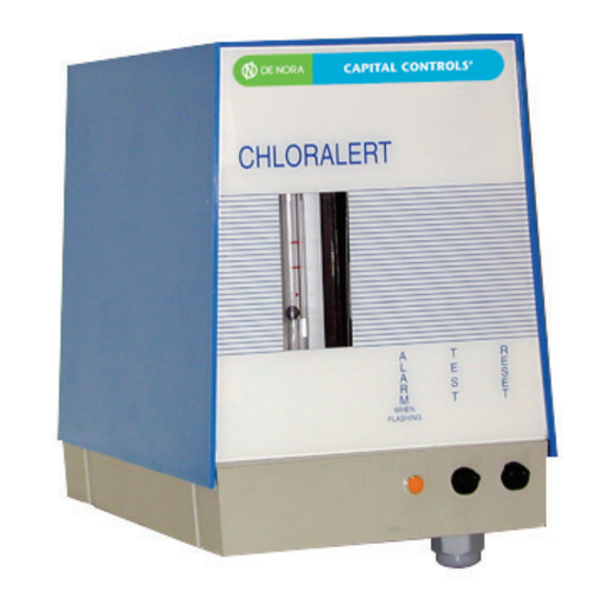
- Page 1 Instruction Manual CHLORALERT Series T17CA4000 Chlorine Gas Leak Detector CAPITAL CONTROLS ® - 1 - 325.6030.7...
- Page 2 De Nora Water Technologies, Inc. cannot be responsible for the overall system design of which our equipment may be an integral part of or any unauthorized modifications to the equipment made by any party other that De Nora Water Technologies, Inc.
- Page 3 Should any question arise which may not be answered specifically by these instructions, they should be directed to De Nora Water Technologies for further detailed information and technical assistance. DNWT takes all possible precautions in packing each equipment item to prevent damage during shipment.
-
Page 4: Chloralert Internal View
PAGE INTENTIONALLY LEFT BLANK 325.6030.7 - 4 -... -
Page 5: Table Of Contents
TABLE OF CONTENTS INTRODUCTION ................................6 General Description ..................................... 6 TECHNICAL SPECIFICATIONS ............................7 MODEL NUMBER BREAKDOWN ........................... 9 Standard accessories .................................... 9 INSTALLATION ................................10 Location ........................................10 Mounting ........................................10 Sampling line ......................................11 Electrical wiring ....................................11 OPERATION, MAINTENANCE AND TESTING ......................12 Electrolyte filling at start up ................................12 Electrolyte renewal after operation .............................12 Sample flow rate ....................................12... -
Page 6: Introduction
INTRODUCTION General Description The De Nora Water Technologies chlorine gas leak detector, CHLORALERT™ T17CA4000, continually monitors air samples for the presence of chlorine. It is usually installed in chlorine usage and storage areas to protect personnel and equipment. A small internal air blower continually draws a sample of air into the Chloralert. The flowmeter and valve enable a fixed amount of air to be passed over the surface of the special electrolyte, where the chemical reaction takes place in presence of chlorine. -
Page 7: Technical Specifications
TECHNICAL SPECIFICATIONS Power supply: 120 Vac, 60 Hz 220 Vac, 50 Hz 110 Vac, 50 Hz Detection level: 1 ppm (3 mg/m ), or 3 ppm (9 mg/m Relay contacts: DPDT, 10 A. 240 Vac, resistive load or 28 Vdc Cell response time: Instantaneous Warm up time:... -
Page 8: Outline Dimensions
325.6030.7 - 8 -... -
Page 9: Model Number Breakdown
MODEL NUMBER BREAKDOWN T17CA4 Basic CHLORALERT™ Alarm Design 1 - Standard 2 - Fail Safe Electrical Requirement 10 - 120 Vac, 60 Hz 20 - 220 Vac, 50 Hz 30 - 110 Vac, 50 Hz Design Level Alarm Level 3 - 1 ppm, Fixed 4 - 3 ppm, Fixed Standard accessories 1 kit P/N 614S071U0l including:... -
Page 10: Installation
INSTALLATION Location The Chloralert™ should ideally be mounted outside the area to be monitored. However it can be mounted in the contaminated area if it is considered absolutely necessary. The location should be such that the ambient temperature never falls below -20 °C (-4°F) nor rises above 65 °C (149°F). It should never be mounted in direct sunlight and should be protected from the weather if mounted outside. -
Page 11: Electrical Wiring
Electrical wiring Cable gland on the Chloralert™ will accept a cable of diameter between 5 to 10 mm. Refer to the following drawings to connect the power supply and the external signals to the Chloralert. Figure 4 - Electrical Wiring - 11 - 325.6030.7... -
Page 12: Operation, Maintenance And Testing
START-UP, OPERATION AND MAINTENANCE Electrolyte filling at start up Refer to figure 5. Switch off power supply or unplug instrument. Remove cover rising it. Disconnect cell cable from terminal block noting carefully position of each cable. Disconnect exhaust tubing from the cell. Unscrew the four retaining screws and drop bottom half of cell from the upper for filling. -
Page 13: Circuit Performance Check
Circuit performance check Simultaneously press and hold down both TEST and RESET switches. The alarm LED must change from the steady condition to flashing and the sampling fan stays activated. This checks that the electronic circuits are operating properly. If it is desired to check external circuits the RESET switch must be released: any remote device connected to the relay will be actuated. -
Page 14: Maintenance Procedures
MAINTENANCE PROCEDURES Note: disconnect power supply before removing the instrument cover. Measuring cell maintenance Refer to Section 5.1 and 5.2 of this manual. Flowmeter 6.2.1 For Model T17CA4100 Clean tube and float whenever dirt has accumulated causing malfunction. Using a screwdriver loosen and slide the top tube retainer ring towards the enter of the tube. Remove tube by pulling forward. -
Page 15: Ce Declaration
CE DECLARATION Chlorine Gas Leak Detector Model T17CA4000 is in conformity with the following standards: EN 56681-2 (Generic emission standard, industrial environment) • EN 56682-2 (Generic emission standard, industrial environment) • Following the provisions of directives: “Electromagnetic compatibility 89/336/CEE, modified by directive 92/31/CEE". - 15 - 325.6030.7... - Page 16 Design improvements may be made without notice. Represented by: De Nora Water Technologies 3000 Advance Lane Colmar, PA 18915 ph +1 215 997 4000 • fax +1 215 997 4062 web: www.denora.com mail: info.dnwt@denora.com DEC 2018 ®Registered Trademark. © 2018. All Rights Reserved.
Need help?
Do you have a question about the Capital Controls CHLORALERT T17CA4000 Series and is the answer not in the manual?
Questions and answers