Table of Contents
Advertisement
Quick Links
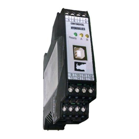
Continental Hydraulics Installation Manual
CEM-PA-B
Product Description:
This closed loop PID amplifier, drives a single solenoid proportional pressure or flow
control valve coil up to 2.6A. It is suitable to provide precise closed loop control in
pressure, force, or velocity systems. This module uses traditional PID error correction to
provide stable control in dynamic systems.
A wide range of analog signals are accepted. User may select either voltage or current
input mode. These inputs are easily scaled to match system requirements. Input
command can be ramped. PID variables are adjustable over a wide range. The
Amplifier is easily switched from open loop to closed loop control.
Min and Max output current are adjustable. Output characteristics can be independently
customized. The module is disabled if the coil outputs are shorted or open. If command
current signal is outside of the proper range, the module is disabled. PWM and Dither
are user adjustable.
This module is easily adapted to a variety of system requirements. All variables are user
adjusted with easy to use software on your Microsoft Windows laptop. Control variables
are stored in non-volatile memory internal to the module. All variables can be read by
the laptop, and reproduced exactly on other modules.
Page 1 of 24
CEM-PA-B
CHI 1020688
01/2016
Advertisement
Table of Contents

Subscribe to Our Youtube Channel
Related Manuals for Continental Hydraulics CEM-PA-B


Summary of Contents for Continental Hydraulics CEM-PA-B
- Page 1 Continental Hydraulics Installation Manual CEM-PA-B Product Description: This closed loop PID amplifier, drives a single solenoid proportional pressure or flow control valve coil up to 2.6A. It is suitable to provide precise closed loop control in pressure, force, or velocity systems. This module uses traditional PID error correction to provide stable control in dynamic systems.
-
Page 2: Table Of Contents
Continental Hydraulics Installation Manual Table of Contents Information Description Page # Technical Data ………………………………………………………………….. 3 Steps to install and configure a new application ……………………………. 4-5 Module Mounting Location …………………………………………………….. 5 Power Supply …………………………………………………………………… 5 Wiring to Valve ………………………………………………………………….. 5 Circuit Diagram …………………………………………………………………. 6 LED Definitions …………………………………………………………………. -
Page 3: Technical Data
Continental Hydraulics Installation Manual Technical data [VDC] 12… 30 (incl. ripple) Supply voltage Current requirement [mA] 60 + solenoid current External protection [A] 3 medium time lag Reference voltage [V] 8 (max. 25 mA load) Digital inputs [V] logic 0: < 2 [V] logic 1: >... -
Page 4: Steps To Install And Configure A New Application
Continental Hydraulics Installation Manual Steps to install and configure a new application: All parameters are adjusted using VEA-BUSB-A programming cable and CHI-PC Microsoft Windows application. 1. Mount the module in suitable location. See page 5. 2. Connect the power supply, valve connections and enable. -
Page 5: Module Mounting Location
Continental Hydraulics Installation Manual 14. Set the N_RANGE:X to the maximum pressure rating of the pressure sensor. For a 0- 210 bar pressure transducer, set N_RANGE:X to 210 bar. This setting should be the same or greater than the SYS_RANGE value. -
Page 6: Circuit Diagram
Continental Hydraulics Installation Manual Circuit Diagram Page 6 of 24 CEM-PA-B CHI 1020688 01/2016... -
Page 7: Led Definitions
Continental Hydraulics Installation Manual LED Definitions LEDs Description of the LED function Identical to the READY output. OFF: No power supply or ENABLE is not activated ON: System is ready for peration GREEN Flashing: Error discovered Only active when SENS = ON... -
Page 8: Parameter List
Continental Hydraulics Installation Manual CEM-PA-B Function Parameter layout MODE Ref Page Command Parameter Help / Description EN EN English MODE EXP Standard / Expert mode SENS AUTO Malfunction monitoring [ON / OFF /AUTO] EOUT 0 Output signal if not ready [0.01%]... -
Page 9: Command Parameter Descriptions
Continental Hydraulics Installation Manual Command Parameter Descriptions LG (Changing the language) Command Parameters Unit Group x= DE|EN Either English or German can be selected for the help texts. After changing the language settings, the ID button in the menu bar (CHI-PC) must be pressed (module identification). -
Page 10: Eout
Continental Hydraulics Installation Manual EOUT (Output signal if not ready) Command Parameters Unit Group EOUT x= -10000… 10000 0.01 % Output value in case of a detected error or a deactive ENABLE input. A value (degree of valve opening) for use in the event of a sensor error (or the module is disabled) can be defined here. -
Page 11: Ainmode (Signal Scaling Mode)
Continental Hydraulics Installation Manual AINMODE The AINMODE is used to define the type of analog input signals being used. The standard default setting of AINMODE is EASY. In the EASY mode the SIGNAL:W/X/V (see page 13) are only available in the most commom 0-10 volt or 4-20mA values. - Page 12 Continental Hydraulics Installation Manual AINMODE - Analogue input scaling parameters Command Parameters Unit Group FUNCTION i = A|B a b c x AIN:I a= -10000… 10000 b= -10000… 10000 c= -10000… 10000 0.01% = V|C This command offers an individual scalable input. The following linear equation is used for the scaling.
-
Page 13: N_Range:x
Continental Hydraulics Installation Manual N_RANGE:X (Sensor nominal pressure) Command Parameter Unit Group N_RANGE:X X x= 10… 10000 EASY N_RANGE (nominal range) is used to define the pressure range of the sensor. This value should be always same as or higher than SYS_RANGE. The control parameter cannot be calculated correctly in case of wrong values. -
Page 14: Ra:up / Ra:down (Ramp Times)
Continental Hydraulics Installation Manual RA (Command signal ramp time) Command Parameter Unit Group RA:I i= UP|DOWN x= 1… 600000 Two quadrant ramp function. The ramp time is separately set for UP and DOWN ramps. A:DOWN A:UP Page 14 of 24... -
Page 15: C:p, C:i, C:d, C:d_Ti, C:d_Ff
Continental Hydraulics Installation Manual C:P, C:I, C:D C:D_TI, C:FF Control parameters (PID controller) Command Parameter Unit Group I= P|I|D|D_T1|FF x= 0… 10000 0.01 x= 0… 30000 0.1 ms x= 0… 1200 0.1 ms :D_T1 x= 0… 1000 0.1 ms x= 0… 10000 0.01 %... -
Page 16: C:i_Lim, C:i_Act
Continental Hydraulics Installation Manual C:I_LIM, C:I_ACT Integrator control function Command Parameter Unit Group C:I_LIM x= 0… 10000 0.01 % C:I_ACT x= 0… 10000 0.01 % The integrator function is controlled by this command. C:I_LIM Limitation of the integrator range (faster control function by reduced pressure overshoots). -
Page 17: Min
Continental Hydraulics Installation Manual MIN (Deadband compensation) MAX (Output scaling) TRIGGER (Response threshold for the MIN parameter) Command Parameters Unit Group MIN:I x= 0… 6000 0.01 % MAX:I x= 3000… 10000 0.01 % TRIGGER x= 0… 3000 0,01 % With this command, the output signal is adjusted to the valve characteristics. With the MAX value the output signal (the maximum valve current) will be defined. -
Page 18: Signal:u
Continental Hydraulics Installation Manual SIGNAL:U (Output polarity) Command Parameter Unit Group SIGNAL:U + | - This command is used to define the output polarity. 0 % to 100 %, normal output 100 % to 0 %, changed output polarity CURRENT (Rated solenoid current) -
Page 19: Pwm
Continental Hydraulics Installation Manual PWM (PWM Frequency) Command Parameter Unit Group x= 61… 2604 The frequency can be changed in defined steps (61 Hz, 72 Hz, 85 Hz, 100 Hz, 120 Hz, 150 Hz, 200 Hz, 269 Hz, 372 Hz, 488 Hz, 624 Hz, 781 Hz, 976 Hz, 1201 Hz, 1420 Hz, 1562 Hz, 1736 Hz, 1953 Hz, 2232 Hz and 2604 Hz). -
Page 20: Ppwm / Ipwm
Continental Hydraulics Installation Manual PPWM (P gain of the current loop) IPWM (I gain of the current loop) Command Parameters Unit Group PPWM x= 0… 30 IPWM x= 1… 100 The PI current controller for the solenoids is parameterized with these commands. -
Page 21: Failure Monitoring
Continental Hydraulics Installation Manual Failure monitoring Following possible error sources are monitored continuously when SENS = ON/AUTO: Source Fault Characteristic Command signal PIN Out of range or broken The output will be switched 9/10 wire off. 4... 20 mA Feedback signal PIN 14... -
Page 22: Troubleshooting
Continental Hydraulics Installation Manual Troubleshooting It is assumed that the device is in an operable state and there is communication between the module and the CHI-PC. Furthermore, the valve control parameterization has been set with the assistance of the valve data sheets. - Page 23 Continental Hydraulics Installation Manual FAULT CAUSE / SOLUTION ENABLE is active, the In many cases you may have a hydraulic problem. READY LED is active and Electrical problems may be: the pressure is instable. Electrical noise at the wire of the power supply.
- Page 24 Continental Hydraulics Installation Manual FAULT CAUSE / SOLUTION ENABLE and START The capability of the hydraulic system has to be checked. Deactivate PIN 6 for (PIN 6) are active, the open loop control and check the pressure build up and down time. If the system...
Need help?
Do you have a question about the CEM-PA-B and is the answer not in the manual?
Questions and answers