Table of Contents
Advertisement
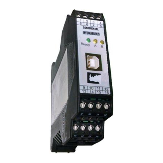
Description:
This adaptable power amplifier is configurable to drive either single or dual solenoid, or two
independent proportional valve coils up to 2.6A. A wide range of analog or digital signals are
accepted dependent on the configuration. User may select either voltage, current or digital input
mode. These inputs are easily scaled to match system requirements.
The CEM-AA-B module has three selectable function modes:
Function mode AA for operating one single or dual solenoid Proportional Control Valve
Function mode A-B for operating independently two single solenoid Proportional Control
Valves
Function mode RA, This mode accepts 3 independent switch inputs, each which has
independently adjustable speed and ramp controls. Inputs are additive, for up to 8 unique
preset speed and ramp profiles.
Independent Ramp of acceleration and deceleration, IMIN and IMAX, PWM, DITHER settings are
programmable. In addition the valve characteristics can also be linearized via 10 X-Y points per
solenoid output.
The module is disabled if the coil outputs are shorted or open. If command current signal is
outside of the proper range, the module is disabled.
This module is easily adapted to a variety of system requirements. All variables are user adjusted
with easy to use CHI-PC software on your Microsoft Windows laptop. Control variables are
stored in non-volatile memory internal to the module. All variables can be read by the laptop, and
reproduced exactly on other modules.
Page 1 of 33
Continental Hydraulics Installation Manual
CEM-AA-B
CEM-AA-B
CHI 1020611
01/2016
Advertisement
Table of Contents

Subscribe to Our Youtube Channel
Related Manuals for Continental Hydraulics CEM-AA-B


Summary of Contents for Continental Hydraulics CEM-AA-B
- Page 1 User may select either voltage, current or digital input mode. These inputs are easily scaled to match system requirements. The CEM-AA-B module has three selectable function modes: Function mode AA for operating one single or dual solenoid Proportional Control Valve ...
-
Page 2: Table Of Contents
Table of Contents Information Description Page # Technical Data - All Function Modes for CEM-AA-B …………………….………..…………… 3 LED Indications - All Function Modes …………………………………………………………… 4 Steps to install and configure a new application ……………………….………………………. 5 Module Mounting Location ………………………………………….…………………………….. 6 Power Supply ………………………………………………………………………………….……... -
Page 3: Technical Data - All Function Modes For Cem-Aa-B
Continental Hydraulics Installation Manual Technical Data - All Function Modes: 12… 30 (incl. ripple) Power supply [VDC] 60 (depending on type of solenoid, two solenoids are Power consumption max. active) External fuse 3 medium time lag Reference voltage 8 (maximum 25 mA) Digital inputs logic 0: <... -
Page 4: Led Indications - All Function Modes
Continental Hydraulics Installation Manual LED Indications - All Function Modes: LED's Description of the LED function GREEN + YELLOW 1. Chasing light (over all LEDs): The bootloader is active. No normal functions are possible. 2. All LEDs flash shortly every 6 s: An internal data error was detected and corrected automatically! The module still works regularly. -
Page 5: Steps To Install And Configure A New Application
Continental Hydraulics Installation Manual Steps to install and configure a new application: All parameters are adjusted using VEA-BUSB programming cable and CHI-PC Microsoft Windows application. 1. Mount the module in a suitable location 2. Connect the power supply and valve solenoids 3. -
Page 6: Module Mounting Location
Continental Hydraulics Installation Manual Module Mounting Location: This module is to be mounted in a cabinet for protection from the local environment. Ensure there is adequate free space around the module to allow for cooling air flow. This module is designed to snap onto an industry standard 35mm DIN rail. -
Page 7: Circuit Diagram Function Aa
Continental Hydraulics Installation Manual Circuit Diagram Function AA Page 7 of 33 CEM-AA-B CHI 1020611 01/2016... -
Page 8: Terminal Identification Aa Function
Continental Hydraulics Installation Manual CEM-AA-B Function AA Input and Output Terminals Connection Supply PIN 7 Power supply (see technical data) 0 V (GND) Power supply (ground). PIN 8 Attention, PIN 8 and PIN 11 are connected internally. PIN 11 is used as the GND potential for the command and feedback signals.. -
Page 9: Parameter List Function Aa
Continental Hydraulics Installation Manual Parameter List Function AA Ref Page MODE Command Parameter Help / Description FUNCTION AA Function mode (AA / A-B / RA) Press ID button after selection EN EN English MODE EXP Standard / Expert mode SENS... -
Page 10: Circuit Diagram Function A-B
Continental Hydraulics Installation Manual Circuit Diagram Function A-B Page 10 of 33 CEM-AA-B CHI 1020611 01/2016... -
Page 11: Terminal Identification A-B Function
Continental Hydraulics Installation Manual CEM-AA-B Function A-B Input and Output Terminals Connection Supply PIN 7 Power supply (see technical data) 0 V (GND) Power supply (ground). PIN 8 Attention, PIN 8 and PIN 11 are connected internally. PIN 11 is used as the GND potential for the command and feedback signals. -
Page 12: Parameter List Function A-B
Continental Hydraulics Installation Manual Parameter List Function A-B Ref Page MODE Command Parameter Help / Description FUNCTION A-B Function mode (AA / A-B / RA) Press ID button after selection EN EN English MODE EXP Standard / Expert mode SENS... -
Page 13: Circuit Diagram Function Ra
Continental Hydraulics Installation Manual Circuit Diagram Function RA Page 13 of 33 CEM-AA-B CHI 1020611 01/2016... -
Page 14: Terminal Identification Ra Function
Continental Hydraulics Installation Manual CEM-AA-B Function RA Input and Output Terminals Connection Supply PIN 7 Power supply (see technical data) 0 V (GND) Power supply (ground). PIN 8 Attention, PIN 8 and PIN 11 are connected internally. PIN 11 is used as the GND potential for the command and feedback signals. -
Page 15: Parameter List Function Ra
Continental Hydraulics Installation Manual Parameter List Function RA Ref Page MODE Command Parameter Help / Description STD EXP-SD EXP-4Q FUNCTION RA Function mode (AA / A-B / RA) Press ID button after selection EN EN English MODE EXP Standard / Expert mode... -
Page 16: Function
Continental Hydraulics Installation Manual Parameter Descriptions FUNCTION (Function mode) Command Parameters Unit Group FUNCTION x= AA|A-B|RA The general Operating function of the module will be defined by this command. AA: Functionality for directional valves with two solenoids and analogue input signals... -
Page 17: Sens
Continental Hydraulics Installation Manual SENS (Failure monitoring) Command Parameters Unit Group SENS x= ON|OFF|AUTO This command is used to activate/deactivate the monitoring functions (4… 20 mA sensors, output current, signal range and internal failures) of the module. All monitoring functions are active. Detected failures can be reset by deactivating the ENABLE input. -
Page 18: Pin:6
Continental Hydraulics Installation Manual PIN:6 (Choice of the additional function of S1/PIN 6) Command Parameters Unit Group FUNCTION PIN:6 x= USCALE | RAMP This parameter defines the functionality of digital input PIN:6 USCALE: PIN 6 = active, USCALE will not scale the output. -
Page 19: Lim
Continental Hydraulics Installation Manual LIM (Signal monitoring) Command Parameters Unit Group FUNCTION LIM:I i= A|B 0.01% x= 0… 2000 x= 0… 2000 0.01% The signal monitoring deactivates the output current and the READY output if the input signal leaves the permitted range after scaling. This function makes it possible to detect a short circuit or cable break of a joystick or potentiometer. -
Page 20: Pol
Continental Hydraulics Installation Manual POL (Output polarity) Command Parameters Unit Group FUNCTION POL:I i= A|B x= +|- x= +|- Valves with one solenoid: This command allows a switch over of the output signal direction (after the MIN-MAX function). POL:A + Input signal 0… 100 %, nominal output current 0… 100 %. -
Page 21: Ain
Continental Hydraulics Installation Manual AIN (Analogue input scaling Continued) This command offers an individual scalable input. The following linear equation is used for the scaling. Output = A/B ∙ (Input – C) “C” value is the offset (e.g. to compensate the 4 mA in case of a 4… 20 mA input signal). -
Page 22: Aa:i / Ab:i (Ramp Time)
Continental Hydraulics Installation Manual AA and AB (Ramp function/Acceleration time) Commando Parameters Unit Group FUNCTION i= UP|DOWN AA:I x= 1… 120000 AB:I x= 1… 120000 Two quadrant ramp function. The first quadrant means the ramp up and the second quadrant means the ramp down time. The ramp time is related to 100 % signal step. -
Page 23: Rmode
Continental Hydraulics Installation Manual RMODE (Choosing ramp function) Command Parameters Unit Group FUNCTION RMODE x= SD|4Q Choosing the ramp function. This command allows the switching between a set point related ramp function (SD), which makes it possible to assign an individual ramp time for each command value, and a four quadrant ramp function (4Q) with set point independent ramp times for acceleration and deceleration in both directions. - Page 24 Continental Hydraulics Installation Manual RA:0 … RA:7 (Ramp function / Acceleration time) Command Parameters Unit Group FUNCTION RA:I i= 0… 7 RA – SD Mode x= 1… 120000 Presetting of the ramp times. Functionality depends on command RMODE. RMODE = SD: In this mode every command value has its own ramp time.
-
Page 25: Cca / Ccb
Continental Hydraulics Installation Manual CCA (Characteristics linearization channel A) CCB (Characteristics linearization channel B) Command Parameters Unit Group FUNCTION CCA:I 0… CCMODE=ON CCB:I x= -10000… 10000 0.01 % y= -10000… 10000 0.01 % A user defined signal characteristic can be set by this function. For activating the parameter CCMODE has to be switched to ON. -
Page 26: Cc (Characteristics Linearization)
Continental Hydraulics Installation Manual CC (Characteristics linearization) Command Parameters Unit Group FUNCTION CC:I -10… CCMODE=ON x= -10000… 10000 0.01% y= -10000… 10000 0.01% A user defined signal characteristic can be set by this function. For activating the parameter CCMODE has to be switched to ON. -
Page 27: Min
Continental Hydraulics Installation Manual MIN (Overlap compensation) MAX (output scaling) TRIGGER (threshold value of MIN function) Command Parameters Unit Group FUNCTION i= A|B MIN:I x= 0… 6000 0.01 % MAX:I x= 5000… 10000 0.01 % TRIGGER x= 0… 3000 0.01 % The output signal is adapted to the valve by these commands. - Page 28 Continental Hydraulics Installation Manual Command Parameters Unit Group FUNCTION i= A|B MIN:I x= 0… 6000 0.01% MAX:I x= 5000… 10000 0.01% TRIGGER x= 0… 3000 0.01% The output signal is adapted to the valve by these commands. The output signal (the maximum valve current) is defined by the MAX:I value.
-
Page 29: Current
Continental Hydraulics Installation Manual CURRENT (Nominal output current) Command Parameters Unit Group FUNCTION CURRENT:I X i= A|B x= 500… 2600 CURRENT x= 500… 2600 The nominal solenoid current is set with this parameter. The DITHER and also the MIN/MAX parameter always refer to the selected current range. -
Page 30: Pwm
Continental Hydraulics Installation Manual PWM (PWM frequency) Command Parameters Unit Group FUNCTION PWM:I i= A|B x= 61… 2604 x= 61… 2604 The frequency can be changed in the defined steps (61 Hz, 72 Hz, 85 Hz, 100 Hz, 120 Hz, 150 Hz, 200 Hz, 269 Hz, 372 Hz, 488 Hz, 624 Hz, 781 Hz, 976 Hz, 1201 Hz, 1420 Hz, 1562 Hz, 1736 Hz, 1953 Hz, 2232 Hz and 2604 Hz). -
Page 31: Ppwm / Ipwm
Continental Hydraulics Installation Manual PPWM (Solenoid current controller P gain) IPWM (Solenoid current controller I gain) Command Parameters Unit Group FUNCTION i= A|B PPWM:I x= 0… 30 IPWM:I x= 1… 100 PPWM x= 0… 30 IPWM x= 1… 100 The PI current controller for the solenoids is parameterized with these commands. -
Page 32: Process Data (Monitoring)
Continental Hydraulics Installation Manual PROCESS DATA (Monitoring) Command Description Unit FUNCTION Command value after input scaling Command value after linearization Command value to current controller Output current of solenoid A Output current of solenoid B Command Description Unit FUNCTION Command value after input scaling channel A... -
Page 33: Failure Monitoring
Continental Hydraulics Installation Manual Failure monitoring Following possible error sources are monitored continuously when SENS = ON / AUTO: Source Fault Characteristics Command signal PIN 9 / 10 or Out of range The power stage is deactivated. Command signal PIN 14 / 13, 4...20mA...
Need help?
Do you have a question about the CEM-AA-B and is the answer not in the manual?
Questions and answers