
Related Manuals for Alpha Technologies Cordex HP 48 1.2kW

Summary of Contents for Alpha Technologies Cordex HP 48 1.2kW
- Page 1 Cordex 48-1.2kW Rectifier Shelf System Technical Guide: 010-619-J0 Effective: 10/2018 Alpha Technologies Ltd.
- Page 3 Copyright Copyright © 2018 Alpha Technologies Ltd. All rights reserved. Alpha is a registered trademark of Alpha Technologies. No part of this documentation shall be reproduced, stored in a retrieval system, translated, transcribed, or transmitted in any form or by any means manual, electric, electronic, electromechanical, chemical, optical, or other-wise without prior explicit written permission from Alpha Technologies.
-
Page 5: Table Of Contents
ABLE OF ONTENTS ........1 AFETY Safety Wording/Symbols . - Page 6 Network Connection and Remote Communication ... . . 16 Controller Connections ......17 .
- Page 7 PECIFICATIONS Cordex HP 48 1.2kW Switched Mode Rectifier ....51 CXCM1 HP Controller ......54...
- Page 8 IST OF IGURES Figure 1: Single Shelf ........6 Figure 2: Dual Shelf.
- Page 9 Sample Maintenance Log......43 Table 8: Specifications: Cordex HP 48 1.2kW, Switched Mode Rectifier ..51 Table 9: Specifications: CXCM1 HP Controller .
-
Page 11: Safety
Keep it in a safe place. Review the drawings and illustrations contained in this manual before proceeding. If there are any ques- tions regarding the safe installation or operation of this product, contact Alpha Technologies or the nearest Alpha representative. -
Page 12: Battery Safety
: Lethal voltages are present within the power system. Always assume that an electrical WARNING connection or conductor is energized. Check the circuit with a voltmeter with respect to the grounded portion of the enclosure (both AC and DC) before performing any installation or removal procedure. •... - Page 13 • Batteries are hazardous to the environment and should be disposed at a recycling facility. Consult the battery manufacturer for recommended local authorized recyclers. 010-619-J0 Rev B Page 3...
- Page 14 010-619-J0 Rev B Page 4...
-
Page 15: Introduction
Introduction Scope of the Manual This manual explains the installation, interconnection, and operation of the Alpha Cordex CXRF-HP 48-1.2 kW 48Vdc power and distribution systems that contain the CXCM1 series of controllers (includes CXCM1+ and CXCM1 HP). Product Overview These 48Vdc power and distribution systems incorporate the high performance (HP) series of 48V 1.2kW Cordex rectifier modules and are specifically designed for restricted space installation. -
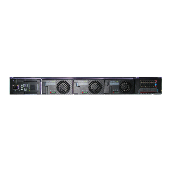
Page 16: Figure 1: Single Shelf
Figure 1: Single Shelf Figure 2: Dual Shelf Figure 3: 2RU Shelf 010-619-J0 Rev B Page 6... -
Page 17: Features
Features Rectifier The Cordex CXRF-HP series of 48V 1.2kW rectifier modules employ high frequency, switch mode tech- nology featuring high power conversion efficiency. All internal semiconductor devices operate under “soft-switching” conditions and exhibit very low power loss. The reduced power loss leads to lower thermal stress on the semiconductors and thus improves reliability. -
Page 18: Mechanical Locking Clip
When the “locate module” command has been received from the controller, the LEDs behave in a distinctly different way so that the rectifier is easier to visually identify among adjacent rectifiers. This state is entered when commanded via the controller. The LEDs flash in a distinct pattern repeating every two seconds. -
Page 19: Ac Inrush/Transient Suppression
• For voltages above 277Vac, power factor and total harmonic distortion may be derated. Up to 320Vac, the rectifier may not be operational but shall not suffer any damage. 3.1.8 AC Inrush/Transient Suppression An external surge suppressor is not required at the AC input, modules are protected from input lightning and transient surges in accordance with IEEE/ANSI C62.41 Category B3. -
Page 20: Distribution
Distribution 3.2.1 4.8kW System Distribution Module 0300165 (Cordex CXRF-HP 48-1.2kW center mounting 2RU shelf for systems up to 4.8kW) The distribution component uses up to four bullet-type breakers that can be factory configured for either 4 load breakers or 2 load/2 battery breakers, and up to ten GMT fuse positions. The distribution module also allows for termination of two battery strings and includes a 150A battery shunt. -
Page 21: Overview Of The Cxcm1 Hp
Overview of the CXCM1 HP CXC HP in-shelf controllers have a small organic LED (OLED) display. This display shows 30 charac- ters total (five lines high, six characters wide) and the controller has three navigation buttons and one reset button. The in-shelf display has three main operating modes: dashboard, menu and screen saver. -
Page 22: In-Shelf Display: Menu
Figure 8: In-Shelf Controller Dashboard Screens D C - - 4 8 5 4 . 0 9 V Output Voltage 1 0 3 . 1 A Output Current F l o a t Battery Mode Nominal System D C - - 2 4 Output Output Type Voltage... -
Page 23: In-Shelf Controller Buttons
Table 1: In-Shelf Controller Full Menu (Continued) (Sheet 2 of 2) Menu Label Description Backup Backup the controller application and configuration to a file on a USB device Restore Restore the controller application and configuration from a file on a USB device Upgra... -
Page 24: Overview Of The Cxcm1
Overview of the CXCM1+ The Cordex controller is mounted in the rectifier system shelf bringing advanced monitoring technology to the rectifiers. This compact system controller is designed for seamless operation and set up of Alpha power systems, and is equipped with the complete range of software features, including the following: •... -
Page 25: Lcd Screen
Figure 12: Cordex CXCM1+ model system controller front panel System Status LEDs LCD Screen Display pushbutton toggle switch (V/A) Reset - push once for soft reset Hold 3 seconds to reset IP address Ethernet Port 3.4.2 LCD Screen The controller front panel uses a 4-digit LCD screen to monitor the system voltage (V) and current (A). A push-button toggle switch allows the user to alternate the display reading. -
Page 26: Ethernet Port
front panel. A full defragmentation may take up to 20 minutes to perform, do not power down the controller during this time. : Refer also to the software manual – always select the Reset menu item before pressing the reset NOTE button. -
Page 27: Controller Connections
A step-by-step connection wizard – provided to establish remote communications with your controller – is available via the Alpha website (http://www.alpha.ca/downloads). 3.4.10 Controller Connections Next to the CXCM1+, on the left side of the shelf, are terminal block connections for the system control I/O;... - Page 28 010-619-J0 Rev B Page 18...
-
Page 29: Inspection
Alpha Technologies is not responsible for damage caused by improper packaging of returned products. If you have any questions before you proceed, call Alpha Technologies: 1 888 462-7487. 010-619-J0 Rev B... - Page 30 010-619-J0 Rev B Page 20...
-
Page 31: Installation
Installation : This power system is suitable for installation in Network Telecommunication Facility locations NOTE where the NEC applies, and in OSP applications. This chapter is provided for qualified personnel to install the product. Mount the unit horizontally in a clean and dry environment. -
Page 32: Removing A Cxrf
Insert rectifiers by placing the module on the shelf bottom and sliding the module into the rear connector (inside of the shelf). Apply pressure on the front of the module to engage the rear connector in the shelf receptacle. A locking clip is provided to secure the rectifier into the shelf. : Do not force a module into position if it does not seat properly. -
Page 33: Removing The Cxcm1 Hp
Figure 15: Removing a CXRF or CXCM1 or CXCM1+ Removing the CXCM1 HP To remove the CXCM1 HP: 1. Push up and hold the latch while removing the controller. 2. Pull from the location noted in the following image to remove the controller. : When removing the controller in a live system that has an LVD, ensure that the LVD override CAUTION jumper is set to correct position to avoid possible service disruption. -
Page 34: Figure 16: Removing The Cxcm1 Hp
Figure 16: Removing the CXCM1 HP 2. Pull here to remove the controller from the shelf. 1. Push up here and hold to release latch while removing the controller from the shelf. 010-619-J0 Rev B Page 24... -
Page 35: Wiring And Connections
Wiring and Connections This chapter provides cabling details and notes on cable sizing for DC applications with respect to the shelf. : Refer to the drawings located at the rear of the manual. NOTE Safety Precautions : Hazardous AC voltages may be present. Ensure power at the AC service panel is off before WARNING attempting work on the AC connections. -
Page 36: Ac Input
Table 2: Recommended AC Supply Configuration Number of Rectifiers on AC Circuit Breaker, Exact Value AC Input (Vac) Feed to Use (A) 120/240 208/220/240 An external surge protection device is not required. The rectifiers are protected by internal MOVs. AC Input : Route the AC input wires in flexible or rigid conduit as far away as possible from the DC power CAUTION wires to minimize EMI disturbances. -
Page 37: Calculating Output Wire Size Requirements
Figure 18: AC Cord Strain Relief for IRU Shelves Calculating Output Wire Size Requirements Wire size is calculated by first determining the appropriate maximum voltage drop requirement. Using the formula below calculate the CMA wire size requirement. Determine the size and number of conduc- tors required to satisfy the CMA requirement. -
Page 38: Figure 19: Dc Output Connections
Figure 19: DC Output Connections : Make sure the applicable fuse has been removed before unplugging the corresponding NOTE connector. 1. To connect a DC output cable, use needle nose pliers to pull out the appropriate plug-in connector. Apply gentle clamping force to the pliers to avoid breaking the connector. 2. -
Page 39: Dc Output For Model 0300165 (Maximum 4800W)
4. Insert fuses into the slots. The maximum allowable output current of the GMT block is 40A distributed over up to eight poles. The bigger left pole can accommodate a current of up to 10A with a fuse of up to 15A. The smaller poles can each accommodate a current of up to 8A with a fuse of up to 10A. -
Page 40: Figure 21: Dc Output Connections (Four Load Breaker Configuration Shown)
Figure 21: DC Output Connections (Four Load Breaker Configuration shown) : Cabling must be done with enough slack to allow the distribution assembly to be locked into NOTE place. Chassis and Site Ground Connections : For safety reasons, ensure the system is properly bonded to the building’s ground grid. WARNING This power system is suitable for installation as part of a Common Bonding Network (CBN), and is intended to be used in a DC-C configuration (common DC return). -
Page 41: Figure 22: Breaker Return Connections (Four Load Breaker Configuration Shown)
Slide the connection point assembly back into the distribution module and secure with the thumbscrew lock. Note the cable(s) and the connection points positioned for proper access. Figure 22: Breaker Return Connections (Four Load Breaker Configuration shown) Breaker Hot Connections Connect to the four load breaker hot (–) termination pairs using 1/4"... -
Page 42: Dc Output For Model 030-835-20/ 030-845-20 (Bulk Distribution)
Connect via screw terminations, hot (–) and return (+), for each fuse position. The maximum allowable output current of the GMT box is 30A distributed over some or all of the ten GMT fuse positions. The largest current that can be accommodated is 10A with a fuse of up to 15A. If using a 15 A fuse, leave the adjacent fuse position(s) empty. -
Page 43: Analog Inputs
Bundle the signal cables together and route them through the entry holes of the shelf. Figure 24: Signal Wiring Terminal Blocks (030-851-20 shown) 6.9.1 Analog Inputs : Ensure the correct polarity is used for all input cable terminations. CAUTION Ensure the correct polarity is used for all input cable terminations.The analog input channels are used to monitor various types of electrical signals. -
Page 44: Alarm (Relay) Outputs
(dry contact – usually located on the equipment requiring monitoring). This method allows the digital input to receive (or not receive) a Ground signal on an alarm. Figure 25: Digital Input Connection Method Programming the Digital Input The digital input channels can be programmed for “active high” or “active low. Active high indicates, “alarm on the presence of a ground signal”... -
Page 45: Lvd Control (Load Disconnect Or Battery Disconnect)
6.9.4 LVD Control (Load Disconnect or Battery Disconnect) The disconnect option is controlled by and connected internally to relay K1. LVD Inhibit Should it be necessary to remove a CXCM1 series controller, the customer connection board (on the front of the shelf) provides shorting pins (JP2) to inhibit (or override) the LVD Control function. See the customer connections drawings. - Page 46 010-619-J0 Rev B Page 36...
-
Page 47: Operation
Operation Main Rectifier States Rectifier operation has five main states; each state is distinct and necessary for the operation of the rectifier. • • Start Delay • Soft Start • Normal Operation • Turning Off 7.1.1 The rectifier is in the Off state immediately after power is applied to the rectifier or after a rectifier shut- down (remote or local shutdown, AC shutdown, OVP or thermal shutdown). -
Page 48: Turning Off
7.1.5 Turning Off The Turning Off state is entered because a short delay is required before the rectifier actually turns off to take care of any initialization requirements. When this short delay has elapsed, a transition to the Off state is made. Main Rectifier Modes In addition to main rectifier states, there is a set of main rectifier modes. -
Page 49: Can Bus Communication
Table 5: Output Current/Power Modes (Continued) (Sheet 2 of 2) Output Current/Power Mode Output current and power limit have been reduced due to: Short circuit foldback Short circuit at the output. mode Internal fault foldback Internal fault. mode CAN Bus Communication The CAN bus is used for commands and data transfer between the rectifier and controller to configure the rectifier with system settings and to monitor rectifier status. -
Page 50: Table 6: Factory Ranges And Defaults
Table 6: Factory Ranges and Defaults (Continued) (Sheet 2 of 2) Setting Range (minimum to maximum) Default Current Limit / Power Limit Alarm Enable/Disable Enable Remote Shutdown Enable/Disable Enable Ramp Test Enable/Disable Enable : OVP cannot be set below the present system/FL/EQ/BT voltage setting or the safe mode voltage NOTE of 51.4V. -
Page 51: System Startup
System Startup Check System Connections • Ensure AC is off, battery is disconnected, and all power modules are removed from the shelf. • Verify the polarity of all connections. Verify AC and Power The Shelf • Install one power module. •... -
Page 52: Hard Reset
8.4.3 Hard Reset A hard reset of the controller can be performed by unplugging the module. This procedure will restart the microprocessor if the front panel (soft) reset button fails to operate. : Move the LVD control jumper to the override position before unplugging the controller. The CAUTION load and batteries are still connected. -
Page 53: Maintenance
Maintenance Although very little maintenance is required with Alpha systems, routine checks and adjustments are recommended to ensure optimum system performance. Qualified service personnel should do repairs. The following table lists a few maintenance procedures for this system. These procedures should be performed at least once a year. - Page 54 1. Slide the module 10 cm (4") out of the shelf and wait two minutes for module capacitors to discharge. 2. Remove the bottom screw that secures the front panel to the module chassis 3. Slide the front panel out. 4.
-
Page 55: Warranty And Service Information
Warranty and Service Information 10.1 Technical Support In Canada and the USA, call toll free 1-888-462-7487. Customers outside Canada and the USA, call +1-604-436-5547. 10.2 Warranty Statement For full information details review Alpha's online Warranty Statement at www.alpha.ca. 10.3 Product Warranty Alpha warrants that for a period of two (2) years from the date of shipment its products shall be free from defects under normal authorized use consistent with the product specifications and Alpha’s instructions, the terms of the manual will take precedence.The warranty provides for repairing, replacing or issuing... - Page 56 010-619-J0 Rev B Page 46...
-
Page 57: Certification
Certification CSA (Canadian Standards Association also known as CSA International) was established in 1919 as an independent testing laboratory in Canada. CSA received its recognition as an NRTL (Nationally Recognized Testing Laboratory) in 1992 from OSHA (Occupational Safety and Health Administration) in the United States of America (Docket No. - Page 58 010-619-J0 Rev B Page 48...
-
Page 59: Glossary
Glossary Alternating Current ACCT Alternating Current Current Transducer ADIO Analog-digital input-output ALCO Alarm cutoff Controller Area Network Current Transducer Cordex series; e.g. CXC for Cordex™ System Controller Cordex™ Controller CXC HP Cordex™ Controller High Performance Cordex™ DC-DC Converter Cordex™ Rectifier Direct current DCCT Direct Current Current Transducer... - Page 60 IPv4 Internet Protocol version 4 IPv6 Internet Protocol version 6 International Organization for Standardization Liquid Crystal Display Light Emitting Diode Low voltage disconnect LVBD Low voltage battery disconnect Media Access Control; e.g. MAC address Management Information Base; a database of entities most often associated with SNMP Metal Oxide Varistor Multiplexer NEBS...
-
Page 61: Specifications
Specifications 13.1 Cordex HP 48 1.2kW Switched Mode Rectifier Table 8: Specifications: Cordex HP 48 1.2kW, Switched Mode Rectifier (Sheet 1 of 3) Specifications: Cordex HP 48-1.2kW, Switched Mode Rectifier Power Module Output Voltage: 42 to 58Vdc within rated limits... - Page 62 Table 8: Specifications: Cordex HP 48 1.2kW, Switched Mode Rectifier (Continued) (Sheet 2 of 3) Specifications: Cordex HP 48-1.2kW, Switched Mode Rectifier : This equipment has been tested and found to comply with the limits for a Class A digital device, NOTE pursuant to part 15 of the FCC Rules.
- Page 63 Table 8: Specifications: Cordex HP 48 1.2kW, Switched Mode Rectifier (Continued) (Sheet 3 of 3) Specifications: Cordex HP 48-1.2kW, Switched Mode Rectifier Operating -40 to +65°C (-40 to 149°F) -40 to +80°C (-40 to 176°F) [de-rated output Temperature: power] Storage Temperature: -40 to +80°C (-40 to 176°F)
-
Page 64: Cxcm1 Hp Controller
13.2 CXCM1 HP Controller Table 9: Specifications: CXCM1 HP Controller (Sheet 1 of 3) Specifications: Basic Unit, CXCM1 HP Input Voltage: 12 to 60Vdc within rated limits Current: <200mA @ 52Vdc, <400mA @ 26.5Vdc, <800mA @ 13.2Vdc MTBF: 95,000 hours (10.9 years), with display off OLED 84,000 hours @ 10% usage, 9,800 at 100% usage, at 25°C Safety: CSA 60950-1-03 IEC/EN 60950-1 CE Mark... - Page 65 Table 9: Specifications: CXCM1 HP Controller (Continued) (Sheet 2 of 3) Specifications: Basic Unit, CXCM1 HP Temperature: -40 to 75°C (-40 to 167°F) operating -40 to 80°C (-40 to 176°F) storage Humidity: 5% to 95% RH non-condensing Elevation: -500 to +4000m (-1640 to 13124 ft) Hardware CPU: ARM A8...
-
Page 66: Cxcm1+ Controller
Table 9: Specifications: CXCM1 HP Controller (Continued) (Sheet 3 of 3) Specifications: Basic Unit, CXCM1 HP The above information is valid at the time of publication. Consult factory for up-to-date ordering information. Specifications are subject to change without notice. 13.3 CXCM1+ Controller Table 10: Specifications: CXCM1+ Controller (Sheet 1 of 3) Specifications: Basic Unit, CXCM1+... - Page 67 Table 10: Specifications: CXCM1+ Controller (Continued) (Sheet 2 of 3) Specifications: Basic Unit, CXCM1+ : This equipment has been tested and found to comply with the limits for a Class A digital device, NOTE pursuant to part 15 of the FCC Rules. These limits are designed to provide reasonable protection against harmful interference in a residential installation.
- Page 68 Table 10: Specifications: CXCM1+ Controller (Continued) (Sheet 3 of 3) Specifications: Basic Unit, CXCM1+ Mounting: Modular on Cordex CXRF 48-1.2kW series shelves (options for 1RU horizontal or 2RU vertical orientation depending on shelf) Relay Outputs: Seven (7) Form C, 60Vdc 1A maximum Digital Inputs: Two (2), 0 to 60Vdc Analog Inputs:...
- Page 88 Fax: +90 216 370 23 68 www.alphapower.mx www.alpha.com.tr Alpha Technologies Ltd. Due to continuing product development, Alpha Technologies reserves the right to change specifications without notice. 010-619-J0 (10/2018) Copyright © 2018 Alpha Technologies. All Rights Reserved. Alpha® is a registered trademark of Alpha Technologies.
Need help?
Do you have a question about the Cordex HP 48 1.2kW and is the answer not in the manual?
Questions and answers