
Subscribe to Our Youtube Channel
Related Manuals for Condec UPC5100


Summary of Contents for Condec UPC5100
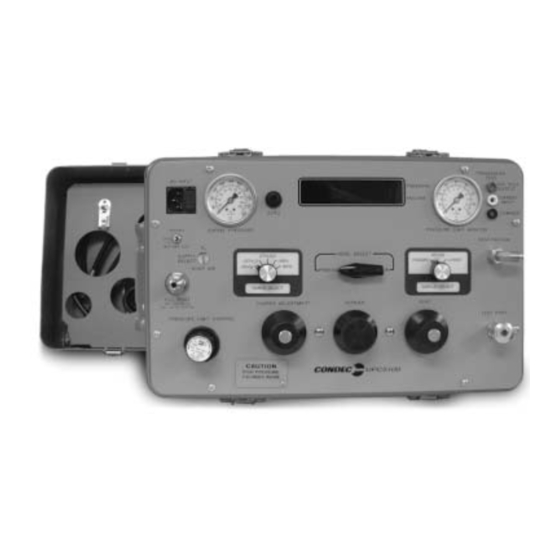
- Page 1 UPC5100/UPC5110 Portable & Rack-mountable Pneumatic Pressure Calibration Console Operation & Maintenance Manual CONDEC Sales Phone No. (888) 295-8475 CONDEC Web Site: www.4condec.com 63257...
-
Page 2: Table Of Contents
4.2 Maintenance and Service Procedures ..........14 4.2.1 UPC5100/UPC5110 Panel/Chassis - Removal and Installation ......14 4.2.2 Nitrogen Cylinder Assembly (PN 59531) - Removal and Installation . - Page 3 Model Number System ......................36 Available Ranges, Conversions and Resolutions ..............37 Options - Replacement Kits ....................... 38 Specifications ..........................39 UPC5100/UPC5110 Warranty and Return Policy ................... 51 UPC5100/UPC5110 Return Material Authorization Form............... 52...
-
Page 4: About This Manual
Introduction Utilizing microprocessor technology, the UPC5100 and rack-mounted UPC5110 instruments offer a combination of features, performance, versatility, and reliability not previously available in a single, self-contained pressure calibration instrument. Some of the features are listed below: •... - Page 5 The UPC5100 has an internal, rechargeable 12 volt lead acid battery, that provides a minimum of six hours of complete portability when fully charged. An ON/OFF and battery test switch is provided to conserve energy when the instrument is not in use and to provide the operator with battery voltage status during use.
- Page 6 The following schematic provides an overview of the UPC5100/UPC5110’s function. Figure 1-1. UPC5100/UPC5110 Flow Diagram Introduction...
-
Page 7: Operation
The following sections explain the various procedures for operating the UPC5100/UPC5110. Pressure Cylinder Filling Procedure To initially fill or refill the internal pressure cylinder (2015 PSI max) of the UPC5100/UPC5110, see Figure 2-1 and proceed by following these steps: NOTE: Check the Nitrogen Fill Port markings on Pressure Console, some units may be 2216 PSI max. -
Page 8: Shop Air Operation
Figure 2-2. Initial Setup Procedure NOTE: UPC5100 shown, AC input (7) and fill port (4) are on back side of UPC5110 Rack Mountable Calibrator. 6. Optional - if the current (4.0000 to 20.000 mA) measurement features are used, connect the provided transducer test cable (PN 55092), to the transducer test jacks (14). -
Page 9: Pressure Measurement Sequence (Gage Only Unit)
0-100.00 mV by 0.02 mV Table 2-1. Display Select Switch (16) NOTE: UPC5100/UPC5110 reads a 4-20 mA signal only, but will display as either 4-20 mA or 20-100 mV. The test cable connector wiring is as follows: CONNECTOR PIN DESIGNATION... -
Page 10: Vacuum Measurement Sequence
Figure 2-3. Pressure or Vacuum Measurement Sequence NOTE: UPC5100 shown, AC Input (7) and Fill Port (4) are on back side of UPC5110 Rack Mountable Calibrator. Vacuum Measurement Sequence See Figure 2-3 above and proceed as follows: 1. Turn the MODE SELECT valve (10) to the VACUUM position. -
Page 11: Battery Operation
The UPC5100/UPC5110 can be operated and recharged by connecting to a standard AC outlet via the line cord (supplied). The battery re-charge cycle time is approximately 16 to 20 hours with the ON/OFF switch in the OFF position. -
Page 12: Calibration
• The CONDEC Repair Lab is equipped to do calibrations on CONDEC calibrators and pressure standards. Calibrations include a certification and are traceable to N.I.S.T (see “UPC5100/UPC5110 Return Material Authorization Form” on page 52). -
Page 13: Zero/Span Calibration
Zero/Span Calibration Selecting the position on the Condec Calibration Module (PN 60109) places the instrument into its ZERO/SPAN calibration mode. The display is shown in Figure 3-2. ZERO/SPAN Figure 3-2. Zero/Span calibration for Gage-Only Units The unit needs to be calibrated to only one positive and one bi-directional range. All bi-directional ranges are calibrated over 0 to +14 PSI and 0 to -14 PSI. -
Page 14: Linearity And Hysteresis Calibration
Install the Condec Calibration Module (PN 60109) and select the position of the rotary switch on the LYN/HYS module. This places the UPC5100/UPC5110 into its linearization/hysteresis calibration mode. The display is shown in Figure 3-3 below. NOTE: The zero/span calibration needs to be performed prior to linearity and hysteresis calibration. -
Page 15: Shunt Resistor Calibration
If 100% (±0.05%) is not obtained, repeat the zero/span calibration sequence. Shunt Resistor Calibration To place the UPC5100/UPC5110 into shunt calibration mode, install the Condec Calibration Module (PN 60109) and select the position of the rotary switch. The display is shown in Figure 3-4. -
Page 16: Permanent Data Storage
NOTE: If the display reading is off, set the Current Generator to 0, and press the ENTER button on the Condec Calibration Module. Set the Current Generator for 20 mA output. The display will read 20.000. If the display reading is off, press the ENTER button on the module. -
Page 17: Maintenance And Service
Maintenance and Service This section outlines the mechanical and basic electrical repair procedures for the UPC5100/UPC5110. Troubleshooting Use Table 4-1 below for information on troubleshooting the UPC5100/UPC5110. Symptom Problem Remedy No lit display Unit will not energize Check fuse, check power source, check... -
Page 18: Nitrogen Cylinder Assembly (Pn 59531) - Removal And Installation
Nitrogen Cylinder Assembly (PN 59531) - Removal and Installation NOTE: Condec strongly recommends that the internal nitrogen supply cylinder be pressure-tested and re-certified every five years from date cylinder was manufactured per U.S. DOT. 3AL Regulation, Title 49 CFR, parts 173 and 178. -
Page 19: Orion-2D Manifold Removal (Pn 55286)
5. To disassemble the isolation valves (inner valve), first remove the valve needle (18) by turning the gear (6) clockwise. 6. Loosen and remove the valve housings (19) using the isolation valve housing removal socket (68509) and socket wrench. UPC5100/UPC5110 Operation & Maintenance Manual... -
Page 20: Orion-2D Manifold - Vernier Control Disassembly
7. Remove the valve stem seats (8) and valve needle seats (9) using the needle-nose pliers. 8. Remove the inner and outer O-rings (28, 27) and back-up rings (31, 30) from the valve stem seats and wash all parts in solvent (de-natured alcohol). 9. -
Page 21: Orion-2C Manifold - Valve Seat Installation
14. Apply a small amount of Krytox grease to the threads of the valve needles (18) and install ISOLATION into the valve by turning counter-clockwise. Rotate the gear until the needle just stops at the seat. UPC5100/UPC5110 Operation & Maintenance Manual... -
Page 22: Orion-2D Manifold - Panel Installation
4.2.8 ORION-2D Manifold - Panel Installation Tools required: 7/16" open end wrench Phillips screwdriver hex wrench (.061") snoop, liquid leak gas detector (PN 64781) 11/32" open end wrench (thin) 1. If not already done, remove the panel knobs from the (pressure), , and valves... - Page 23 VENT knob insert (4). Do not use excessive torque when adjusting valve. The seat can be damaged. Caution 31. Tighten the set screws (25) with the .061" hex wrench. The valve is now adjusted. VENT UPC5100/UPC5110 Operation & Maintenance Manual...
-
Page 24: Chassis Mounted Regulator (Pn 55502) - Removal, Installation And Adjustment
MONITOR pull regulator knob outward and turn counter-clockwise. When closed, push knob inward. VENT valve should be left open. 2. Rotate SUPPLY SELECT to N position. 3. Turn customer supplied N source valve to the off position, vent pressure line, then install line to fill port of UPC5100/UPC5110. Maintenance and Service... -
Page 25: Pressure Limit Control (Pn 58409) - Regulator Removal And Installation
5. Fill the cylinder to approximately 1000 PSIG and check all fittings for leaks. If there are no leaks, fill nitrogen supply cylinder to maximum pressure. See Section 2.1 on page 4 for cylinder refilling procedure. 6. Install panel/chassis assembly in its enclosure as described in Section 4.2.1 on page 14. UPC5100/UPC5110 Operation & Maintenance Manual... -
Page 26: Supply Pressure (Pn 59730) And Pressure Limit Monitor (Pn 59706) Gauges-Removal And Installation
4.2.12 Supply Pressure (PN 59730) and Pressure Limit Monitor (PN 59706) Gauges - Removal and Installation Tools required: 7/16" wrench 9/16 " wrench A/R 1/4" wide Teflon tape (PN 60575) snoop, liquid leak gas detector (PN 64781) Removal: 1. Vent any remaining nitrogen from cylinder to atmosphere. Disconnect power cord from power source. 2. -
Page 27: Test Port Filter (Pn 54188) - Removal, Cleaning And Installation
2. Remove front panel from its enclosure as described in Section 4.2.1 on page 14, and carefully place on a bench top. 3. Remove nylon tubing from the compressed air port (top/input) and the vacuum port (front/output) of the vacuum generator. 4. Using nutdriver remove nylon spacers, (PN 60472), and remove vacuum generator. UPC5100/UPC5110 Operation & Maintenance Manual... - Page 28 NOTE: Some vacuum generators are mounted with screws and nuts or adhesive. 5. Clean the vacuum generator by using compressed air. Do not use solvent for cleaning. Warning Removal and Cleaning - Aluminum Body (PN 54965) 1. Remove ORION-2D manifold from front panel as described in Section 4.2.3 on page 16, and carefully place on a bench top.
-
Page 29: Vacuum Control Regulater (Pn 59765) - Removal, Installation And Adjustment
4. Turn the MODE SELECT knob on the front panel to VACUUM position. 5. Turn RANGE SELECT switch to +/- 28 in. Hg. 6. Energize UPC5100/UPC5110 and allow warmup time. 7. Push the ZERO button (less than 5 seconds), then close the VENT valve. -
Page 30: Inlet Check Valve, Nitrogen Fill Port (Pn 60263) - Removal, Disassembly And Installation
11. Install panel/chassis assembly in its enclosure as described in Section 4.2.1 on page 14 4.2.17 Inlet Check Valve, Nitrogen Fill Port (PN 60263) - Removal, Disassembly and Installation Remove the check valve if it does not hold the pressure of the N cylinder. -
Page 31: Ac Power/Emi Line Filter (Pn 58870) - Removal And Installation
BATTERY TEST 3. Plug in the harness connector to its receptacle J7 on the CPU board and install cable clamp. 4. Install panel/chassis assembly in its enclosure as described in Section 4.2.1 on page 14. UPC5100/UPC5110 Operation & Maintenance Manual... -
Page 32: Power Switch (Pn 58878) For Non-Battery Units - Removal And Installation
4.2.21 Power Switch (PN 58878) for Non-Battery Units - Removal and Installation Tools required: Phillips screwdriver 11/16" open end wrench A/R soldering iron A/R shrink sleeving (PN 64567) A/R heat gun Removal: 1. Disconnect the power cord from the power source and line filter. Remove front panel from its enclosure as described in Section 4.2.1 on page 14, and carefully set on a bench top. -
Page 33: Zero Switch (Pn 58886) - Removal And Installation
3. Tighten the switch mounting nut and lock washer from the rear of panel. If wrench is used, do not over tighten, damage may occur to switch. Caution 4. Install panel/chassis assembly in its enclosure as described in Section 4.2.1 on page 14. UPC5100/UPC5110 Operation & Maintenance Manual... -
Page 34: Power Supply Assembly (Battery Units Only) - Removal And Installation
4.2.24 Power Supply Assembly (Battery Units Only) - Removal and Installation 120 VAC input (PN 58727); 220 VAC input (PN 58733). Tools required: Phillips screwdriver Flat blade screwdriver (small) 11/32" open end wrench or nutdriver Removal: 1. Disconnect the power cord from the power source and line filter. Remove front panel from its enclosure, as described in Section 4.2.1 on page 14, and carefully set on a bench top. - Page 35 Adjustment - Battery Voltage Display Reading NOTE: The BATTERY TEST should only be performed with the UPC5100/UPC5110 operating at Zero pressure (VENT valve open) and at the conclusion of the test, the unit's ZERO button will have to be re-pushed to re-zero the instrument.
-
Page 36: Orion-2D Valve Assembly Component Parts List
Orion-2D Valve Assembly Component Parts List Ref #r Description Quantity 57482 Nut, Valve Needle Housing 9/16-18 54401 Locknut 58079 Knob 57889 Knob, Insert 57256 Gear, Spur 40 Teeth 59233 Gear, Spur 18-tooth 55896 Valve Seat 59387 Valve Seat, Stem 59045 Valve, Needle Seat 54540 Housing, Valve Needle... - Page 37 O-RING, ITEM 28, .042 ID O-RING, ITEM 29, .799 ID O-RING, ITEM 32, .424 ID THESE COMPONENTS TO BE INSTALLED AT LOCATION THESE COMPONENTS TO BE INSTALLED “C” ONLY. AT LOCATION B Figure 4-1. ORION-2D, Exploded View UPC5100/UPC5110 Operation & Maintenance Manual...
- Page 38 Figure 4-2. Range Select Switch Wiring Figure 4-3. Display Select Switch Wiring Figure 4-4. N Inlet Check Valve Assembly (PN 60263)
-
Page 39: Model Number System
C - AC Only (220 VAC)*** ≠ D - Battery Operation & 220 VAC ≠ +-------------------------------------------- --+ ≠ DISPLAY ≠ A – Light Emitting Diode (LED) B – liquid Crystal (LCD) *** UPC5100, Available as a Special UPC5100/UPC5110 Operation & Maintenance Manual... -
Page 40: Available Ranges, Conversions And Resolutions
Available Ranges, Conversions and Resolutions NOTE: Non-standard ranges are available by special order. Calibrator Conversion Factors: • kPa = PSI x 6.89476 • in Hg (0˚F) = PSI x 2.036 • Bar = PSI x 0.0689476 • Kg/cm = PSI x 0.070308 •... -
Page 41: Options - Replacement Kits
Note: A small coating of Fluorinated Krytox grease, (PN 55593), should be applied to both sides of O-ring prior to installation. Pressure Trap (Data Sheet # 58621) - PN 58487 Note: For UPC5100/UPC5110 model’s prior to serial number A1300, approximate date prior to 7-9-1990 use Pressure Trap, PN 58492, Data Sheet # 58627. Battery Replacement Kit - PN 55354 Test Port (output) Attachment Swivel Fitting - PN 55291 Test Port (output) Quick-Disconnect Male Hose fitting - PN 60195... -
Page 42: Specifications
Specifications Pressure Specifications: Fill Port: Pressure ranges: +- 0-28 in Hg Style: Quick-disconnect. +- 0-387.00 in H Pressure Rating: 3000 PSIG connected, 2000 PSIG disconnected + 0-2771.0 in H Material: 300 series stainless steel +- 0-96.00 kPa Test Port: + 0-100.00 PSI Available Pressure Pressure Rating: 2000 PSIG... - Page 43 Enamel paint, textured finish UPC5110 Case Dim’s: 19" wide x 8.1" deep x 10.5" high Color: Gray (Case dimensions excluding front handles) Control Panel: Material: Aluminum (5052-H32) Thickness: 0.125 in Finish: Gray enamel paint with black silkscreen nomenclature UPC5100/UPC5110 Operation & Maintenance Manual...
- Page 44 R33 LOCATION. TWIST, DO NOT SOLDER, LEADS TOGETHER. LEAVE APPROXIMATELY 1/4" LEAD LENGTH ON EACH RESISTER. OBSERVE POLARITY OF ICs, CAPACITORS, DIODES, AND TRANSISTORS. NOTE TO CONDEC MANUFACTURING: ITEMS 11 & 31 REQUIRED FOR UPC5200 &UPC5210 UNITS. REMOVE 3- TEST PROCEDURE: (A)KUA7317 ITEM 11 AND SOLDER ITEM 31 ONLY PRIOR TO INSTALLING INTO UPC5000 OR UPC5010.
- Page 45 Figure 8-2. CPU & POWER SUPPLY ASSEMBLY, Sheet 2 (For Non-Battery Units Only) UPC5100/UPC5110 Operation & Maintenance Manual...
- Page 46 Figure 8-3. POWER SUPPLY ASSEMBLY (For Battery Units Only) Maintenance...
- Page 47 DWG NO ANGLE 59037 MFG.ENG. CKD. THIRD ANGLE PROJECTION SV 8/25/87 RICE LAKE WEIGHING SYSTEMS APPROVED DES.ENG. JEW 8/25/87 DR.BY DJS 11/27/00 SCALE SHEET REVISION APPROVED Figure 8-4. CPU ASSEMBLY, Sheet 1 (For Battery Units Only) UPC5100/UPC5110 Operation & Maintenance Manual...
- Page 48 Figure 8-5. CPU Assembly, sheet 2 (For Battery Units Only) Maintenance...
- Page 49 Figure 8-6. CPU & POWER SUPPLY SCHEMATIC, Sheet 1 (For Non-Battery Units Only) UPC5100/UPC5110 Operation & Maintenance Manual...
- Page 50 Figure 8-7. CPU & POWER SUPPLY SCHEMATIC, Sheet 2 (For Non-Battery Units Only) Maintenance...
- Page 51 Figure 8-8. POWER SUPPLY SCHEMATIC, (For Battery Units Only) UPC5100/UPC5110 Operation & Maintenance Manual...
- Page 52 Figure 8-9. CPU SCHEMATIC, Sheet 1 (For Battery Units Only) Maintenance...
- Page 53 Figure 8-10. CPU SCHEMATIC, Sheet 2 (For Battery Units Only) UPC5100/UPC5110 Operation & Maintenance Manual...
-
Page 54: Upc5100/Upc5110 Warranty And Return Policy
UPC5100/UPC5110 Warranty and Return Policy If possible, please save original packing material which is specifically designed for the unit. Should it be necessary to ship the unit back to the factory, a suitable shipping container must be used along with sufficient packing material. -
Page 55: Upc5100/Upc5110 Return Material Authorization Form
Company Name: Street: City, State, ZIP: ATTN: CONDEC • 3 SIMM LANE • DOOR D, UNIT 2A • NEWTOWN, CT 06470 ATTN: PRESSURE PRODUCTS/REPAIR LAB TEL: 888-295-8475 • FAX: 203-364-1556 or 715-234-6967 WEB SITE: www.4condec.com UPC5100/5110 Operation & Maintenance Manual...
Need help?
Do you have a question about the UPC5100 and is the answer not in the manual?
Questions and answers