
Subscribe to Our Youtube Channel
Related Manuals for Condec UPC5000


Summary of Contents for Condec UPC5000
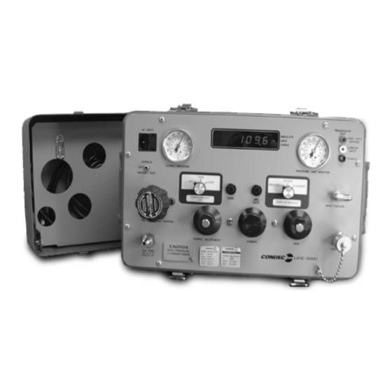
- Page 1 UPC5000/UPC5010 Portable & Rack-mountable Pneumatic Pressure Calibration Console Operation & Maintenance Manual CONDEC Sales Phone No. (888) 295-8475 CONDEC Web Site: www.4condec.com 63256...
-
Page 2: Table Of Contents
Orion 2C Valve Assembly Parts List ..........32 Copyright © 2001 Condec. All rights reserved. Printed in the United States of America. - Page 3 Model Number System ......................46 Available Ranges, Conversions and Resolutions ..............47 Options, Replacement Kits ......................50 Specifications ..........................51 UPC5000/UPC5010 Warranty and Return Policy ................... 52 UPC5000/UPC5010 Return Material Authorization Form............... 53...
-
Page 4: About This Manual
• System Calibration: The instruments can be completely calibrated without being removed from the external case. A separate plug-in Condec Calibration Module (PN 60109) provides access to the computer when calibration is performed. No manual alignment or potentiometer adjustments are required. - Page 5 The UPC5000 has an internal, rechargeable 12 volt lead acid battery, that provides a minimum of six hours of complete portability when fully charged. An ON/OFF and battery test switch is provided to conserve energy when the instrument is not in use and to provide the operator with battery voltage status during use.
-
Page 6: Operation
The following sections explains the various procedures for operating the UPC5000/UPC5010. Pressure Cylinder Filling Procedure To initially fill or refill the internal pressure cylinder (2216 PSI max) of the UPC5000/UPC5010, see Figure 2-1 and proceed by following these steps: 1. Rotate the (1) counter-clockwise until it stops. -
Page 7: Initial Setup Procedure
7. Connect the swivel fitting end (7/16-20) of the test (output) hose to the device-under-test (use adapters if required). Tighten all connections properly. Figure 2-2. Initial Setup Procedure NOTE : UPC5000 shown, AC Input (7) and Fill Port (4) are on back side of UPC5010 Rack Mountable Calibrator. UPC5000/UPC5010 Operation & Maintenance Manual... -
Page 8: Pressure Measurement Sequence For Absolute/Gage Unit
0-100.00 mV by 0.02 mV Table 2-1. Display Select Switch (16) NOTE: UPC5000/UPC5010 reads a 4-20 mA signal only, but will display as either 4-20 mA or 20-100 mV. The test cable connector wiring is as follows: CONNECTOR PIN DESIGNATION... -
Page 9: Pressure Measurement Sequence For Absolute Only Unit
Figure 2-3. Pressure Measurement Sequence (Gage Only) NOTE : UPC5000 shown, AC Input (7) and Fill Port (4) are on back side of UPC5010 Rack Mountable Calibrator. Pressure Measurement Sequence for Absolute Only Unit 1. If only pressure measurements greater than barometric are required, continue to step 1.1. If pressure measurements above and below atmospheric pressure are required, go to Step 2. -
Page 10: Battery Operation
The UPC5000/UPC5010 can be operated and recharged by connecting to a standard AC outlet via the line cord (supplied). The battery re-charge cycle time is approximately 16 to 20 hours with the... -
Page 11: Calibration
Instrument Calibration Set-up The UPC5000/UPC5010 is placed into its calibrate mode by connecting a Condec Calibration Module (PN 60109) via the multi-pin jack. The jack is located behind the small slide plate near the fill port (see Figure 3-1). -
Page 12: Zero/Span Calibration
Install the Condec Calibration Module (PN 60109) and select the position of the rotary switch on the LYN/HYS module. This places the UPC5000/UPC5010 into its linearization/hysteresis calibration mode. The display is shown in Figure 3-3 below. NOTE: The zero/span calibration needs to be performed prior to linearity and hysteresis calibration. For Absolute Only Unit, vacuum pump with PSIA indicator must be used to obtain readings below local barometric pressure. - Page 13 Table 3-2. Linearization and Hysteresis Calibration Sequence When Step 11 is reached, the display changes so that the left most status symbol is . This remains for Step 12 and down to approximately 0.00 PSI. UPC5000/UPC5010 Operation & Maintenance Manual...
-
Page 14: Shunt Resistor Calibration
NOTE: If the display reading is off, set the Current Generator to 0, and press the ENTER button on the Condec Calibration Module. Set the Current Generator for 20 mA output. The display will read 20.000. If the display reading is off, press the ENTER button on the module. -
Page 15: Permanent Data Storage
3. Select the ZERO/SPAN position on the Condec Calibration Module (PN 60109). The UPC5000/UPC5010 displays three dashes on the left side of the display to indicate this mode. 4. Press the ENTER button on the Condec Calibration Module. The UPC5000/UPC5010 display reads zero. -
Page 16: Normal Mode Test
" " to verify the unit's accuracy, then it will return to the normal mode automatically. 3. The pneumatic portion of the calibration is now complete and the pressure standard and the CONDEC Calibration Module can now be disconnected. -
Page 17: Maintenance And Service
Maintenance and Service This section outlines the mechanical and basic electrical repair procedures for the UPC5000/UPC5010. Troubleshooting Use Table 4-1 below for information on troubleshooting the UPC5000/UPC5010. Symptom Problem Remedy No lit display Unit will not energize Check fuse, check power source, check... -
Page 18: Nitrogen Cylinder Assembly Removal (Pn 59531)
Nitrogen Cylinder Assembly Removal (PN 59531) NOTE: Condec strongly recommends that the internal nitrogen supply cylinder be pressure-tested and re-certified every five years from date cylinder was manufactured per U.S. DOT. 3AL Regulation, Title 49 CFR, parts 173 and 178. -
Page 19: Installing New Nitrogen Cylinder Assembly (Pn 59531)
10. Loosen and remove the two panel screws (PN 60837) from the panel front that secure the manifold to the panel. 11. Remove the four retaining nuts that secure the chassis to the panel. 12. Lift the chassis enough to allow the ORION-2C manifold to clear and remove the manifold. UPC5000/UPC5010 Operation & Maintenance Manual... -
Page 20: Orion-2C Manifold, Valve Seat Removal
4.2.5 ORION-2C Manifold, Valve Seat Removal Tools required: A/R solvent (de-natured alcohol) socket wrench 3/4" socket needle housing socket (PN 65580) isolation valve needle housing socket (PN 68509) hex wrench (.050") hex wrench (.061") needle-nose pliers tube fluorinated Krytox grease (PN 55593) electric hand drill No. -
Page 21: Orion-2C Manifold, Vernier Control Reassembly
1. Install a new seat (7) by placing it into the seat well with the needle-nose pliers. Ensure that the seat is centered within the cavity and gently tap it with a blunt end of a drill bit to install. 2. Install the valve needle seat (9) with the smaller diameter end facing outward. UPC5000/UPC5010 Operation & Maintenance Manual... -
Page 22: Orion-2C Manifold, Panel Installation
3. Install new O-rings (28, 27) inside and outside of the valve stem seat. Coat all O-rings and back-up rings (30, 31) with fluorinated Krytox grease before installation. Make sure that the rings are installed in the proper order. 4. Install the valve stem seat (8) by grasping the small diameter end with the needle-nose pliers and positioning in the valve cavity, then gently pushing with the blunt end of a drill bit. -
Page 23: Orion-2C Manifold, Valve Adjustment Procedure
Install the knob on the knob insert while engaging the knob gear (5) with the isolation valve gear (6). 15. Tighten the set screws (25) with the .061" hex wrench. The COARSE valve is now adjusted. UPC5000/UPC5010 Operation & Maintenance Manual... -
Page 24: Pressure Limit Control (Standard Pneumatic), Regulator Removal
NOTE: See Figure 4-2 on page 35. Call CONDEC for replacement part numbers. 1. Wrap two layers of Teflon tape on the pipe threads of each fitting and install into the inlet and outlet of the regulator and ensure that each is oriented properly. Use a bench vise when doing this. -
Page 25: Pressure Limit Control (Tescom), Regulator Removal
(PN 64781) NOTE: See Figure 4-1 on page 33. Call CONDEC for replacement part numbers 1. Wrap two layers of Teflon tape on the pipe threads of each fitting and install into the inlet and outlet of the regulator and ensure that each is oriented properly. -
Page 26: Panel Gauge Removal
7/16" wrench 9/16 " wrench NOTE: Call CONDEC for replacement part numbers. 1. Vent any remaining gas from the nitrogen cylinder to atmosphere. Disconnect the power cord from the power source. 2. Remove front panel from its enclosure as described in Section 4.2.1 on page 14, and carefully place on a bench top. -
Page 27: Test Port Filter (Pn 54188), Removal And Installation
2. Fill the cylinder to approximately 1000 PSIG and check all fittings for leaks. If there are no leaks fill nitrogen supply cylinder to 2200 PSIG. See Section 2.1 on page 3 for cylinder refilling procedure. 3. Install panel/chassis assembly in its enclosure as described in Section 4.2.1 on page 14. UPC5000/UPC5010 Operation & Maintenance Manual... -
Page 28: Inlet Check Valve - Nitrogen Fill Port (Pn 60263)
4.2.19 Inlet Check Valve - Nitrogen Fill Port (PN 60263) Remove the check valve if it does not hold the pressure of the N cylinder. The check valve can be disassembled for cleaning should any debris foul the seat area. Tools required: Phillips screwdriver 7/16"... -
Page 29: Ac Power/Emi Line Filter (Pn 58870), Removal And Installation
BATTERY TEST 3. Plug in the harness connector to its receptacle J7 on the CPU board and install cable clamp. 4. Install panel/chassis assembly in its enclosure as described in Table 4.2.1 on page 14. UPC5000/UPC5010 Operation & Maintenance Manual... -
Page 30: Power Switch (Pn 58878), Removal And Installation (Non-Battery Units)
4.2.23 Power Switch (PN 58878), Removal and Installation (Non-Battery Units) Tools required: Phillips screwdriver 11/16" open end wrench A/R soldering iron A/R shrink sleeving (PN 64567) A/R heat gun Removal: 1. Disconnect the power cord from the power source and line filter. Remove front panel from its enclosure as described in Table 4.2.1 on page 14, and carefully set on a bench top. -
Page 31: Absolute And Zero Switches (Pn 58886), Removal And Installation
1. Connect and solder the wires onto their respective switch terminals (see Table 4-5 and Table 4-6 below): Color Terminal Orange Normally open Green (C) common Green (C) common Table 4-5. Wire to switch terminal connections: Absolute UPC5000/UPC5010 Operation & Maintenance Manual... -
Page 32: Power Supply Assembly, Removal And Installation (Battery Units)
Color Terminal Yellow Normally open Green (C) common Table 4-6. Wire to switch terminal connections: Zero 2. Install the new switch, lock washer and nut through the panel rear. Hand tighten the trim ring from front of panel. 3. Tighten the switch mounting nut and lock washer from the rear of panel. Replace CPU if necessary. If wrench is used, do not over tighten, damage may occur to switch. - Page 33 Adjustment of Battery Voltage Display Reading NOTE: The BATTERY TEST should only be performed with the UPC5000/UPC5010 operating at Zero PSIG (VENT valve open) and at the conclusion of the test, the unit's ZERO button will have to be re-pushed to re-zero the instrument.
- Page 34 3. Connect the leads of a 11.5 VDC power source to the battery cable wires that are connected to TB1 on the power supply board. Adjust potentiometer R9 located on power supply board to illuminate low battery indicator. For LED display type units a red LED in the left center of the display will turn on. For LCD display type units, 5 LED segments in the left of display window will illuminate in the shape of a "U."...
-
Page 35: Orion 2C Valve Assembly Parts List
Setscrew, hex 60837 Screw, MACH Pan Head #10- 32NFx1/2 Phillips Head 300 Series SST 58976 Screw, Self Sealing 53308 Label 59878 Spacer .005 thk 59880 Spacer .007 thk Table 4-7. Orion 2C Valve Assembly Parts List UPC5000/UPC5010 Operation & Maintenance Manual... - Page 36 THESE COMPONENTS TO BE THESE COMPONENTS TO BE THESE COMPONENTS TO BE INSTALLED AT LOCATIONS A & D INSTALLED AT LOCATIONS A & D INSTALLED AT LOCATIONS A & D 25/2X 23/2X 24/3X 35/2X 21/14 25/2X 26/2X THESE COMPONENTS TO BE THESE COMPONENTS TO BE THESE COMPONENTS TO BE INSTALLED AT LOCATIONS B &...
- Page 37 Figure 4-2. Tescom and Standard Pneumatic Regulator Mounting O-ring Insert P/N 66654 Spring Lock Screw Body Insert Poppet Figure 4-3. N Inlet Check Valve Asssembly (PN 60263) Maintenance & Service...
- Page 38 54254 THIRD ANGLE PROJECTION MFG.ENG. JEW 5/7/87 CKD. RICE LAKE WEIGHING SYSTEMS APPROVED SCALE SHEET REVISION DES.ENG. S.V. 5/11/87 DR.BY DJS 6/15/00 APPROVED Figure 4-4. CPU & POWER SUPPLY ASSEMBLY, Sheet 1(For Non-Battery Units Only) UPC5000/UPC5010 Operation & Maintenance Manual...
- Page 39 Figure 4-5. CPU & POWER SUPPLY ASSEMBLY, Sheet 2 (For Non-Battery Units Only) Maintenance and Service...
- Page 40 Figure 4-6. POWER SUPPLY ASSEMBLY (For Battery Units Only) UPC5000/UPC5010 Operation & Maintenance Manual...
- Page 41 -2 = 59040 12- REFERENCE: ASSEMBLY # USED IN RESISTOR, METAL FILM KPW310 R19,R22 SELECT -3 = 59048 KET8924-1 UPC5000 RESISTOR, METAL FILM KPW310W NOTE 19 20K 0.1% 0.1W -4 = 59052 RESISTOR, METAL FILM KPW310AY KET8924-3 UPC5100 13.3K 0.1% 0.1W...
- Page 42 Figure 4-8. CPU Assembly, sheet 2 (For Battery Units Only) UPC5000/UPC5010 Operation & Maintenance Manual...
- Page 43 Figure 4-9. CPU & POWER SUPPLY SCHEMATIC, Sheet 1 (For Non-Battery Units Only) Maintenance and Service...
- Page 44 Figure 4-10. CPU & POWER SUPPLY SCHEMATIC, Sheet 2 (For Non-Battery Units Only) UPC5000/UPC5010 Operation & Maintenance Manual...
- Page 45 Figure 4-11. POWER SUPPLY SCHEMATIC, (For Battery Units Only) Maintenance and Service...
- Page 46 Figure 4-12. CPU SCHEMATIC, Sheet 1 (For Battery Units Only) UPC5000/UPC5010 Operation & Maintenance Manual...
- Page 47 Figure 4-13. CPU SCHEMATIC, Sheet 2 (For Battery Units Only) Maintenance and Service...
-
Page 48: Model Number System
C - Gage or Absolute (Switch-Selectable) +--------------------------------------------------------------+ ≠ DISPLAY A – Light Emitting Diode (LED) B – liquid Crystal (LCD) Available in Gage Only or Absolute Only Available in Gage Only *** UPC5000, Available as a Special UPC5000/UPC5010 Operation & Maintenance Manual... -
Page 49: Available Ranges, Conversions And Resolutions
Available Ranges, Conversions and Resolutions NOTE: All ranges are available in bars only. Calibrator Mode: @ = Gage Only # = Absolute Only $ = Gage or Absolute NOTE : Calibrators have PSI and one conversion as shown in table. RANGE (PSI) 2000/1000/400 1000/500/200... - Page 50 CONVERSION HI/MED/LO HI/MED/LO 100.00/50.00/20.000 0.02/0.01/0.005 7.031/3.5155/1.4062 0.001/0.0005/0.0002 Kg/cm in H 2771.0/1385.6/554.2 0.5/0.2/0.1 Table 6-5. Resolutions (100/50/20 PSI ranges) RANGES RESOLUTION CONVERSION HI/MED/LO HI/MED/LO 50.00/25.00/10.000 0.02/0.01/0.005 in H 1385.5/692.6/277.1 0.5/0.2/0.1 Table 6-6. Resolutions (50/25/10 PSI ranges) UPC5000/UPC5010 Operation & Maintenance Manual...
- Page 51 RANGES RESOLUTION CONVERSION HI/MED/LO HI/MED/LO 15.000/7.500/3.0000 0.002/0.001/0.0005 in H 415.65/207.80/83.13 0.05/0.05/0.01 Table 6-7. Resolutions (15/7.5/3 PSI ranges) Available Ranges, Conversions and Resolutions...
-
Page 52: Options, Replacement Kits
• 15' Long ................PN 55304 • 20' Long ................PN 55310 Fill Port (intput) Hose, with Quick-Disconnect Female fitting: • 5' Long .................PN 55282 • 10' Long ................PN 55313 • 15' Long ................PN 55319 • 20' Long ................PN 55322 UPC5000/UPC5010 Operation & Maintenance Manual... -
Page 53: Specifications
Micro-metering with replaceable soft seat Case: Polystyrene/H.I. ABS Material: Aluminum body, clear anodized aluminum knobs, black anodized. All other parts 300 Carrying Case UPC5000 only: series stainless steel Type: Aluminum case with latched cover and handle Relief Valve: Material Thickness: 0.090 in., nominal... -
Page 54: Upc5000/Upc5010 Warranty And Return Policy
UPC5000/UPC5010 Warranty and Return Policy If possible, please save original packing material which is specifically designed for the unit. Should it be necessary to ship the unit back to the factory, a suitable shipping container must be used along with sufficient packing material. -
Page 55: Upc5000/Upc5010 Return Material Authorization Form
Company Name: Street: City, State, ZIP: ATTN: CONDEC • 3 SIMM LANE • DOOR D, UNIT 2A • NEWTOWN, CT 06470 ATTN: PRESSURE PRODUCTS/REPAIR LAB TEL: 888-295-8475 • FAX: 203-364-1556 or 715-234-6967 WEB SITE: www.4condec.com UPC5000/UPC5010 Return Material Authorization Form...
Need help?
Do you have a question about the UPC5000 and is the answer not in the manual?
Questions and answers