iFix RT809 Series Manual

iFix RT809 Series Manual

Usb universal programmer
Table of Contents

Advertisement

Important information:

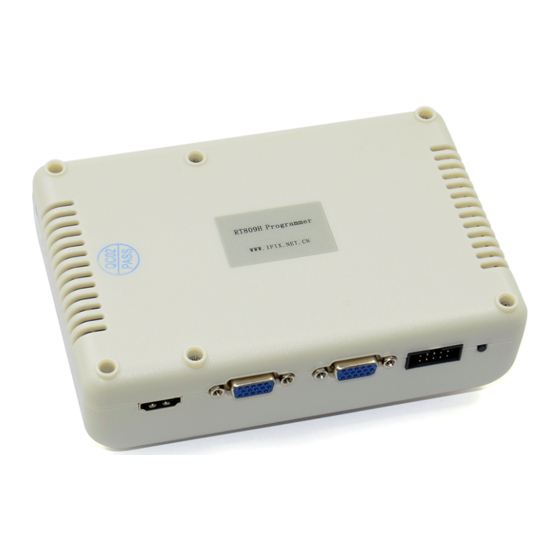
1.This instruction is suitable for RT809H programmer.
2.In order to connect the programmer more conveniently and faster,please connect
the hardware after installing the software.
3.Please read the instruction carefully before using the programmer.
4.Please use the original USB data cable.
Software copyright
User manual copyright
RT809 series of programmers have acquired 6 China National invention patents,any unit or
individual is not allowed to copy,photograph,regenerate,translate or restore to any form of
electronic media readable by other machines,or will be investigated for legal responsibility.
Once there are some differences against this instruction caused by software upgrade please
Copyright Statement
WWW.IFIX.NET.CN
WWW.IFIX.NET.CN
This manual is subject to change without notice.
follow to the software.
Rock Group

Advertisement

Table of Contents
loading
Need help?

Need help?

Do you have a question about the RT809 Series and is the answer not in the manual?

Questions and answers

Summary of Contents for iFix RT809 Series

  • Page 1: Important Information

    WWW.IFIX.NET.CN Rock Group RT809 series of programmers have acquired 6 China National invention patents,any unit or individual is not allowed to copy,photograph,regenerate,translate or restore to any form of electronic media readable by other machines,or will be investigated for legal responsibility.
  • Page 3 Brief 1.1.1 What is RT809F? RT809F is a kind of cost-effective,reliable and fast universal programmer series,suitable for all the computers or laptops based on Pentium IV processors or the better processors.When working it can communicate with the USB2.0 fast port of computer directly,with driver program inside software,which makes installing operation more convenient.
  • Page 4: System Requirement

    1.1.3 Instruction Tissue This instruction consists of three parts: The part one is to introduce RT809H,including the system requirement,software and hardware installing,etc ; The part two is the detailed instruction of software commands and each function; The part three is appendix,including the user support and the wrong message. 1.1.4 System Requirement Minimum system configuration:...
  • Page 5 Left lateral view  Right lateral view  Port instruction  “VGA ISP” can be used as VGA signal output,be connected with the VGA port of the board when flashing. “VGA IN” is the VGA signal input,can be connected with the computer graphics. When unconnected,VGA ISP will output the VGA signal produced by itself;...
  • Page 6 The standard packing: Programmer mainframe  SOP simple soldering board  USB2.0 high-speed cable  VGA connecting line ...
  • Page 7 Software Installation 2.1 Software downloading If you are the first time to use RT809F USB universal programmer,please surf the programmer  official web to download the latest software. http://www.ifix.net.cn/thread-325-1-1.html Like this: Downloaded file:  Need to be unzipped: Open the folder ...
  • Page 8 Attention : The programmer can not be connected before installing.  2.2 Software installing Begin to install,double click this icon;  Click “OK”;  Click “Next”; ...
  • Page 9 Click “Next”;  Click “Next”; ...
  • Page 10 Software installing finished.  Installing the third-party toolchain patch Double click this icon; ...
  • Page 11 Click to unzip;  Wait for the progress bar to finish。 ...
  • Page 12: Driver Installation

    2.4 Driver installation The system of window 7 or more can install the driver automatically,just wait for a moment;  If automatic installation failed,you can install manually,find the hardware without installing driver  in the device manager; Click the right mouse button and click “upgrade driver software”; ...
  • Page 13 Click “Browse”;  Choose D:\RT809F\DRIVER; ...
  • Page 14 Click “OK”and “Next”;  Next install the other 2 drivers in the same way,; ...
  • Page 15 USB serial port driver,the corresponding ground serial port of programmer is COM4;  After installing,open the RT809F software and can see the serial number of the programmer. ...
  • Page 16 The serial number is the only proof for technical support and warranty.Please do not leak, properly  and secretly kept.
  • Page 17 Chapter 3 The Software Instruction Software Main Interface Third-party Toolchain Interface...
  • Page 18 Click this icon recognize intelligently the type of most of the chip,easy to operate. When flash on line,click this icon it will recognize the chip type. Click this icon to check the data content of reading and writing. Click to enter the third-party testing software connecting...
  • Page 19 Click this icon and following menu appears. Setting:change line sequence connecting VGA ISP. Speed adjustment:can adjust the speed when writing. Uninstall the programmer driver Reinstall the programmer driver. When the programmer shows that serial number used,please try to repair the programmer firmware.
  • Page 20 serial port printing switch,when serial port close it shows serial port printing;when it open it shows close. Click drop-down list “Language” to choose different languages.
  • Page 21 Chapter 4 Detailed Operation 93XX,24XX,25XX Chips’ Reading and Writing 4.1.1 The putting place of different chips The putting place of DIP encapsulation chip on RT809F.  The position of SOP encapsulation on the bounce board. ...
  • Page 22 The position of SOP encapsulation on the board. ...
  • Page 23 The position of QSOP 16 pins encapsulation on the socket. ...
  • Page 24 The position of QSOP 16 pins encapsulation on the board. ...
  • Page 25 If the power supply of the chip is 1.8V,it need to add the board.  DIP 8 encapsulation...
  • Page 26 SOP 8 encapsulation 4.1.2 Choose the chip types 93 series chips  Step 1 : Enter the chip printing and click “OK”; Step 2 : Operate only after “OK”shows. 24XX、25XX series chips  Step 1 : After putting the chip well click to get the chip ID;...
  • Page 27 Step 2 : If there are two or more same IDs,choose the same type with the chip waiting to be flashed and click “OK”; 1.1.3 93XX,24XX,25XX series chips reading Step 1 : Click and reading normally; Step 2 : Change the name and path,then click “Save”.
  • Page 28 1.1.4 93XX,25XX,24XX series chips writing Step 1 : Click ; Step 2 : Choose the name of the file that will be written(Bin format); Step 3 : Click at the last,when it shows following information,writing finishes. Laptop KB90XX series EC chip’s writing off line Enter the type into the chip printing blank and click “OK”;...
  • Page 29 The position of the chip on the board.  Then read and write,the saving and loading of the file can refer to the way of 93XX’s.  The hint to show reading and writing smoothly.  PLCC 32 pins chip’s reading and writing The chip with 32 pins or more need PEB-1 expansion board to be used cooperatively.
  • Page 30 Enter the chip type.  The position of the chip on the PEB-1.  It shows writing successfully.  TSOP 48 pins chip’s reading and writing...
  • Page 31 Enter the chip type;  The position of the chip on the PEB-1;  Attention : If to write NAND FLASH,first input the chip type,if there is no please choose “NAND  AUTO”algorithm; If it shows error when using socket,then weld the chip on the test board to test. ...
  • Page 32 Write the 85 series EC chip off line The position of the chip on the board ; ...
  • Page 33 The position of the chip on the socket ;  It shows success. ...
  • Page 34 Attention : The above writing way can write the 85XX series EC chip,but not including 8585 chip(which can choose to write on line) Write the IT85XX Series Laptop EC Chip on Line Input “IT8XXX_ISP_PEB-1” in the “Enter chip printing” blank; ...
  • Page 35 Search for the same type with your laptop in setting;  If there is no the same type,add by yourself according to the line sequence.  Attention :  1. Don’t forget to ground it,and the ground line can not be too slim;...
  • Page 36 2. The flat cable must be cut and plugged as requested,if it isn’t clear enough,there are high-definition photo in BBS to be referred; 3. If 8585 and 8586 can’t be read,please ground the 100pin of the chip. 4. Choose the right type and set the right line sequence,then click “Read” and charge the mainbaord ;...
  • Page 37 4.6.2 Writing data If the mainboard read before hasn’t power off, then can be written directly,or have to click  “Write”first and then charge the mainboard; Load to write the file,open or remove into it directly;  Then click “Write”; ...
  • Page 38 Laptop EC Chip MEC1633 Read&Write by Flying Line...
  • Page 39 Laptop EC Chip KB90 Series off Line Read&Write Input the corresponding chip type in the software interface; ...
  • Page 40 Weld the chip on the board,and please install the components on the board according to the  request;...
  • Page 41 Laptop EC Chip KB90XX Series Reading by Flying Line Flying line diagram  Pin’s corresponding definition ...
  • Page 42 RT809F locking socket pin identify  Attention :  Please fly 6 lines totally,the ground line must be flied well ; The length of the signal line must be within 10cm,EC power supply need the original board supply or the external power source with 3.3V; After flying the 6 lines above well,charge the mainboard first,with the external adapter or charge the chip with 3.3V power source.
  • Page 43 Click “AUTO ISP” in the software interface to identify the chip’s type;  Click “Read”;  Click “Write”; ...
  • Page 44 Referring to 93 chip about how to save and open the file.  4.10 BUF16821 TCON Board GAMMA Voltage Producing Chip Read&Write on Line...
  • Page 45 4.10.1 Board Number Board Number 6870C-3500C,the TCON board frequently-used by LG HD screen of 32 to 55 inch. 4.10.2 Chip Instruction BUF16821 internal ROM has two Banks,but only use one group of them actually,there is the configured data of 36 bytes for each group,which control the two groups of VCOM and the 16 path GAMMA calibrating voltage value by change the internal DAC’s output voltage.
  • Page 46 51 pins,the fourth pin is SDA,the fifth pin is SCL,with a line GND more,remould a ISP upgrading line with the screen lines;and connect it with the 12C expansion port on locking socket of RT809F,then can read and write on line using the screen lines port. Before reading and writing please charge the screen with the 12V power.
  • Page 47 4.10.6 Writing Operation Refer to 93XX chip to save and load file.
  • Page 48 4.11 EPM3064A Read&Write 4.11.1 Chip Instruction Board number : 6870C-0060G,LG LED TV screen LC370WX1 TCON board,CPLD chip type  EPM3064A. Programmer : RT809F  Software version : RT809F_140516 or the updated version  Instruction : EPM3064A and EPM3032A is the MAX3000 series CPLD chip of American ALTERA ...
  • Page 49 Chip pin definition:  Standard JTAG port : TMS TCK TDI TDO 4 signal line with ground line GND  4.11.2 Reading operation Step 1 : Connect the lines correctly and charge the TCON board,the power source is 12V; ...
  • Page 50 Step 2 : Click “Read”.  4.11.3 Writing Operation When writing you can click to encrypt to avoid reading by someone;  Refer to 93 chip to save and open the data. ...
  • Page 51 4.12 S3F Series Samsung Singlechip’s Reading and Writing S3F Series Samsung Singlechip is widely used in the kinds of small home appliances like induction cooker,pressure-cooker and electric frying pan of Midea,Galanz,Povos and other brands.When it needs to read and write the data or change the chip to do repairing,we can use RT809F to do the reading and writing.
  • Page 52 impact it,measure the voltage between 13 pin and 16 pin.If the voltage is lower than 4V,take the RT809F apart first,find two 302 resistors(3k),R63 and R64,and change them to 102 resistor(1k).The RT809F produced after Dec. 2013 has changed the R63/R64 to 1k resistor,so do not need to change anymore.But if the resistor is 1k,the voltage between 13 pin and 16 pin is still low,please remove the 78L05 of the ICSP port board(Useful for PIC series,not for S3F series);...
  • Page 53 Advice for the fresh man to read and write S3F9454 at the first time : First buy some new  S3F9454,then use the attachment in this post link(http://www.ifix.net.cn/thread-12370-1-1.html), write the program file : “奔腾 PC21N-8 S3F9454BZZ-DK94 主板”,if it verified successfully it shows the function to read and write S3F is normal;if it verified wrongly please make a clean system again...
  • Page 54 Recommend : Connect the VPP pin with a 104 tile capacitor to the ground and series connect a  Schottky diode on the VDD line,such as 1N5819,SS14 and so on.Connect the positive pole to the ICSP port board,the negative pole to the side of VDD pin of MCU,which can avoid the VPP pin of MCU to break down the VDD pin because of the poor connection of GND ground line.
  • Page 55  S3F9498 on line read&write connection definition  S3F9488 on line read&write connection definition...
  • Page 56 4.12.6 Reading Operation Step 1 : Open the software,choose MCU type manually;...
  • Page 57 Step 2 : Click “Read”.
  • Page 58 4.12.7 Writing Operation...
  • Page 59 Refer to 93 chip to backup and open the data.  Note 1 : The encryption after writing is optional,MCU can be used also without  encryption.Click “Protect” to encrypt if it is needed. Note 2 : If the RT809F software hints that the program is encrypted after reading,it is no need ...
  • Page 60 4.13.2 Reading Operation Step 1 : Connect the lines correctly,open the software and click “Smart ID”; ...
  • Page 61 Step 2 : If the software hints “Flashing page is 256 bytes”,then skip this step;if it hints “Flashing  page is 264 bytes”then reselect the chip type and read again according to the following picture;...
  • Page 62 4.13.3 Writing Operation Refer to 93 chip to save and load writing file.  4.14 PIC 12F Series SCM’s Reading and Writing 4.14.1 Board Number Board Number : LD40V9-MAC4X,TCL GC32 chip,standby MCU type PIC12F675。PIC12F629,the same method to read and write. 4.14.2 PIC Series Instruction MCU of PIC series is widely used in the standby controlling and power management circuits of...
  • Page 63 because of the static or so on.MCU need to be changed when repairing and then write the program and data in again. 4.14.3 Program Data Source The original program and data supplied by after sale;  The MCU program and data read by self(The precondition is that the MCU hasn’t been encrypted ...
  • Page 64 area blank is “FF3F”,data area blank is “FF00”.If it’s encrypted,it will always be “0000” after reading.The set point of the configuration is usually saved between program area and data area,is only a few bytes,can click “Configuration Word” button to enter the setting interface and set the configuration word of PIC series MCU,then write the chip.
  • Page 65 Step 2 : Click “Read”,RT809F software will read and verify automatically again; ...
  • Page 66 4.14.6 Writing Operation Note 1 : The encryption is optional,MCU also can be used normally without being encrypted.If you  cancel the /CP option of the configuration word before writing,the program area will encrypt automatically after finishing writing and verifying;if cancel the /CPD option the data area will encrypt automatically after finishing writing and verifying.
  • Page 67 Refer to 93 chip to save and open the file.  4.15 RT809F Checking the Printing Information of LCD Board 4.15.1 Software Setting Open the software,there are two icon at the bottom right corner,like the following picture:  1—Parameter Setting: ...
  • Page 68 2—Serial port switch  When showing “Serial print”,the serial port is in the closed state. When showing “Close”,the serial port is in the open state. Mainboard connection  RX TX Lead is on the VGA port,please use the matched VGA line directly. RX TX Lead is on the HDMI port,please use the HDMI line or fly line from the locking socket.
  • Page 69 4.15.3 Operation Step Step 1 : Connect the lines well first,make sure that the RX TX lines connect correctly;  Step 2 : Set the line sequences and bit rate well and save;  Step 3 : After opening the serial port switch,charge the LCD mainboard (The charging order must ...
  • Page 70 Step 5 : The printing information showed. ...
  • Page 71 4.15.4 Checking the printing information using Secure CRT Step 1 : First close the serial print of software;  Step 2 : Open Secure CRT and set;  Step 3 : The following page will appear,set the parameter like the picture showing at the right; ...
  • Page 72 Step 6 : When the icon at the top left corner turns green it shows the successful connection;  Step 7 : Connect the RX TX of LCD mainboard with the programmer;  Step 8 : Charge the LCD mainboard then you can see the printing information. ...

This manual is also suitable for:

Rt809hRt809f

Table of Contents

Save PDF