Page 1
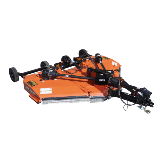
Your life and the lives of others depend on it! Cover photo may show optional equipment not supplied with standard unit. For an Operator’s Manual and Decal Kit in French or Spanish Language, please see your Land Pride dealer. Printed 11/6/18...
Page 2
Machine Identification Record your machine details in the log below. If you replace this manual, be sure to transfer this information to the new manual. If you, or the dealer, have added Options not originally ordered with the machine, or removed Options that were originally ordered, the weights and measurements are no longer accurate for your machine.
Land Pride assumes no responsibility for errors or omissions. Neither is any liability assumed for damages resulting from the use of the information contained herein. Land Pride reserves the right to revise and improve its products as it sees fit. This publication describes the state of this product at the time of its publication, and may not reflect the product in the future.
Page 4
Fixed Clevis Hitch Wear Point ....44 Land Pride Performance Hitch Wear Points ..44 Bar-Tite Hitch Wear Points ....44 Long-Term Storage .
Important Safety Information Important Safety Information Listed below are common practices that may or may not be applicable to the products described in this manual. Safety at All Times Look for the Safety Alert Symbol Careful operation is your best The SAFETY ALERT SYMBOL indicates there is a assurance against an accident.
Lower implement to the ground and Replace parts on this implement implement. follow all shutdown procedures with genuine Land Pride parts only. Attach the chain to the tractor before leaving the operator’s seat to Do not alter this implement in a way drawbar support or other specified perform maintenance.
Page 7
Use Seat Belt and ROPS signals are recommended Keep Riders Off whenever driving on public roads. Machinery Land Pride recommends the use of a CAB or roll-over-protective- Never carry riders on tractor or structures (ROPS) and seat belt implement.
Page 8
Spray soapy water onto the cleaned area. all damaged or missing labels. Order new labels from your Peel backing from label and press label firmly onto the nearest Land Pride dealer. To find your nearest dealer, surface. visit our dealer locator at www.landpride.com.
Page 9
Table of Contents Important Safety Information 70439 818-130C RC Series cutters only Caution! Use 540 rpm power take-off 818-240C RCM Series cutters only Caution! Use 1000 rpm power take-off 70439 70439 818-552C Danger! Rotating Driveline - Keep Away 4-Places (Top of splitter shield, main driveline and 2-wing drivelines) 22296 818-540C...
Page 10
Table of Contents Important Safety Information 70439 818-142C Danger! Rotating Driveline - Keep Away 2-Places (Located on right wing and left wing) 70446 858-950C Warning! Pinching & Crushing Hazard 70446 858-947C Danger! Thrown Object & Rotating Blade Hazard 2-Places (Located on back side of left & right wing) RC(M)3712 &...
Page 11
Table of Contents Important Safety Information 858-949C 70439 Safety Combo 2-Places (Located on the right and left wing decks) 11/6/18 RC(M)3712 & RCG(M)3712 Rotary Cutters 334-203M...
Page 12
Table of Contents Important Safety Information 70439 858-954C Safety Combo RC(M)3712 & RCG(M)3712 Rotary Cutters 334-203M 11/6/18...
Page 13
Table of Contents Important Safety Information 70439 818-229C 1 3/4" x 2 3/4" Amber Reflector 2-Places (Located on front side of left & right wing decks) 70439 838-615C 2" x 9" Amber Reflector 3-Places (Located on front left side of center deck & on right and left side of center axle) 70446 818-230C...
Page 14
Table of Contents Introduction Introduction Land Pride welcomes you to the growing family of new Owner Assistance product owners. This Rotary Cutter has been designed The dealer should complete the Online Warranty with care and built by skilled workers using quality Registration at the time of purchase.
Page 15
RCM3712 ......1000 rpm equipment readily at hand.
Page 16
Section 1: Assembly & Set-up Hitch Types 70450 The following are the five hitch types offered. See your nearest Land Pride dealer should you want to change your hitch set-up. Fixed Clevis Hitch (Optional) Refer to Figure 1-2: Cutter rotation about the tractor drawbar is limited to slot...
Page 17
Table of Contents Section 1: Assembly & Set-up Attach Park Jack Tractor Shutdown Procedure Refer to Figure 1-8: The following are basic tractor shutdown procedures. Follow these procedures and any additional shutdown Attach park jack (#9) to jack mount as shown and procedures provided in your tractor Operator’s Manual secure with attached pin (#8).
Page 18
Table of Contents Section 1: Assembly & Set-up 37298 70457 Fixed Clevis Hitch Hook-up Figure 1-9 Fixed Clevis Hitch Hook-up 9. Shut tractor down properly before dismounting. NOTE: Bolt (#10) and spacer (#11) may be DANGER removed to increase hitch flexibility. If removed, an To avoid serious injury or death: A crushing hazard exists equal number of flat washers (#12) should be added while hooking-up and unhooking implement.
Page 19
Table of Contents Section 1: Assembly & Set-up 37298 70460 LP Performance Hitch Hook-up Figure 1-10 LP Performance Hitch Hook-up 6. Start tractor, raise 3-point arms fully up, and carefully back tractor within close proximity of clevis (#9). DANGER Shut tractor down properly before dismounting. Refer To avoid serious injury or death: A crushing hazard exists to “Tractor Shutdown Procedure”...
Page 20
Table of Contents Section 1: Assembly & Set-up 37298 70461 Bar-Tite Hitch Hook-up Figure 1-11 Bar-Tite Hitch Hook-up 22265 Attach Bar-Tite Hitch to Tractor Drawbar Refer to Figure 1-12: Insert 1" x 5 1/2" hex bolt (#1) through hitch top plate (#2), hitch bushing (#3), hitch wear plate (#4), tractor drawbar (#5), and washer (#6) as shown.
Page 21
Table of Contents Section 1: Assembly & Set-up Restart tractor and back tractor up to cutter hitch until 70460 hole in hitch bushing (#10) aligns with holes in swivel clevis (#9). 8. Shut tractor down properly before dismounting. 9. Insert 1" x 6 1/2" GR5 hex bolt (#2) through swivel clevis (#9) and hitch bushing (#10).
Table of Contents Section 1: Assembly & Set-up 4. Remove hairpin cotter (#1) from both the left and 70462 right transport pins (#2). 5. Pull transport pins (#2) from fold lugs (#3) on both wings. Refer to Figure 1-17: 6. Store transport pins (#2) as shown on light guard brackets (#3) and secure with hairpin cotters (#1).
Page 23
Table of Contents Section 1: Assembly & Set-up 70466 Driveline Assembly Figure 1-18 Driveline Assembly 70465 DANGER To avoid serious injury or death: Make certain driveline yokes are securely fastened at each end. A loose yoke can work free allowing the driveline to rotate uncontrollably causing implement damage and bodily injury or death to anyone nearby.
Page 24
Table of Contents Section 1: Assembly & Set-up Driveline Hook-up to Tractor 70467 DANGER To avoid serious injury or death: • Do not engage power take-off while hooking-up or unhooking the driveline, or while someone is standing near the driveline. A person’s body and/or clothing can become entangled in the driveline.
Table of Contents Section 1: Assembly & Set-up Driveline Hanger Adjustment 70468 Refer to Figure 1-21: Move tractor control lever to extend hydraulic lift cylinder (#1) until pressure against stroke control spacers (#2) is removed. 2. Without relieving hydraulic pressure, Shut tractor down properly before dismounting.
Table of Contents Section 1: Assembly & Set-up 70469 Purge Wing & Center Deck Cylinders Figure 1-23 Driveline Clearance Check Wing Fold Cylinder Refer to Figure 1-23: Refer to Figure 1-23: Check driveline for adequate clearance under all ranges Lower center deck until it is supported by stroke of cutter height.
Table of Contents Section 1: Assembly & Set-up Hook-up LED Lights Remove Shipping Lugs Refer to Figure 1-24: Refer to Figure 1-26: The lead wiring harness (#13) is equipped with a 7-way Tie down lugs are installed on the rear two corners of the round pin connector for connecting to the tractor’s 7-pin center deck for shipping purposes only.
Table of Contents Section 1: Assembly & Set-up Unhook Rotary Cutter 70463 See “Long-Term Storage” on page 45 when storing the cutter for long periods and at end of season. 2. If power take-off is engaged, reduce tractor engine speed to an idle and then disengage power take-off. 3.
Page 29
Table of Contents Section 1: Assembly & Set-up Refer to Figure 1-31: 70460 13. Remove park jack (#3) from left-hand wing deck and attach to jack mount (#15) as shown. Fully insert detent pin (#8) in jack mount to secure park jack. 14.
Page 30
Table of Contents Section 2: Adjustments Section 2: Adjustments Lift Cylinder Adjustment NOTE: Refer to decal (#6) and instructions below for jack alignment and torque value instructions. Refer to Figure 2-3 on page 27: To get best range of motion, put lift cylinder (#2) in bottom NOTE: If cutter is not hitched to a tractor, support hole (as shown) when cutter is supplied with 21"...
Page 31
Table of Contents Section 2: Adjustments Level Center Deck If continuous hinges are too low at the front: a. Loosen jam nuts (#3) several turns. Refer to Figure 2-2 & Figure 2-3 on page 27: b. Tighten coupler nuts (#4) an equal amount to With cutter attached to a tractor, disengage power shorten both leveling rods until hinges (#1) are 1"...
Page 32
Table of Contents Section 2: Adjustments Adjust Cutter Height 8. Select required size and number of stroke control spacers (#2) that will fit on the center hydraulic cylinder (#1). The following spacers are available. NOTE: Make all cutting height adjustments in the field using height of cut grass/material as a guide.
Page 33
Table of Contents Section 3: Operating Instructions Section 3: Operating Instructions Always secure equipment with solid, non-concrete supports • Startup Checklist before working under it. Never go under equipment Hazard control and accident prevention are dependent supported by concrete blocks or hydraulics. Concrete can upon the awareness, concern, prudence, and proper break, hydraulic lines can burst, and/or hydraulic controls training involved in the operation, transport, storage, and...
Page 34
Table of Contents Section 3: Operating Instructions Never carry riders on the implement or tractor. Riders can Improper oil level can cause bearing failure and be a fire • • obstruct the operator’s view, interfere with control of the hazard. Maintain proper gearbox oil level to avoid serious equipment, be pinched by moving components, become injury and property damage.
Page 35
Before checking for leaks, read occurs thereafter. “Avoid High Pressure Fluids Hazard” on page 3. Replace damaged and worn hoses with genuine Land Pride parts. CAUTION To avoid minor or moderate injury: Some tractors are 14. Make repairs to cutter and tractor before continuing with “Blade Operation Inspection”...
Page 36
Table of Contents Section 3: Operating Instructions vehicle sign, relocate sign so it is visible from the back at all Transport Pins times. Always comply with all federal, state, and local laws. IMPORTANT: Always disengage tractor’s power Watch while making tight turns to ensure that the rear •...
Page 37
2. Start tractor and raise both wings up to release any tension on the transport lock pins. Land Pride recommends the Rotary Cutter be equipped 3. Without relieving hydraulics, shut tractor down before with chain guards to stop flying objects when cutting road dismounting.
Page 38
Land Pride Rotary Cutter. fails to rebound. Should this happen you may try It’s now time to do a running operational safety check. It...
Page 39
Try increasing or decreasing ground speed to determine the effect on quality of cut. With a little practice you will be pleased with what you and your Land Pride 12' Folding Rotary Cutter can do. When you are done mowing, need to take a break, or just...
Page 40
The overrunning clutch protects the tractor’s power Land Pride offers two types of safety chain guards to best take-off on tractors that have instant off power take- suit your application: single row chain guards and double offs by allowing the cutter to slowly stop the blades row chain guards.
Page 41
9. Install hydraulic hose (#1) to hydraulic cross fitting (#9) as shown. Tighten hose. Land Pride offers the single duplex accessory so you can 10. Install hydraulic hose (#3) to hydraulic cross fitting change from a 2 duplex cutter to a 1 duplex cutter.
3. Replace wheel rims and tires as needed with contaminations. genuine Land Pride parts. Do not loosen split rim Use a clean cloth to wipe hose ends clean before hardware (#1) until all air pressure in the tire has attaching them to your tractor.
Before each use of the cutter, check that all chain guards are present, undamaged and in working order. Replace any damaged or missing chain guard components as needed. Order only genuine Land Pride parts from your local Land Pride Dealer. DANGER To avoid serious injury or death: Rotary Cutters have the ability to discharge objects at high speeds;...
Table of Contents Section 5: Maintenance & Lubrication Wing Gearbox Driveline Shield Access 37618 Refer to Figure 5-5: To remove shaft guard (#1) at the spindle gearbox, use a flat head screw driver to unsnap latches (#2) on both sides of guard (#1) and slide shaft guard over driveline to expose driveline yoke.
Table of Contents Section 5: Maintenance & Lubrication Clutch Run-In Assembly Reassemble each friction disk (#4) next to the metal plate Refer to Figure 5-6: it was separated from. Install bolts (#3) through end Using a pencil or other marker, scribe a line across the plates and intermediate plates as shown.
Both blades should weigh the same with not more blade! Small nicks can be ground out when sharpening. than 1 1/2 oz. difference. Unbalanced blades will Refer to Figure 5-9 on page 43 when ordering Land Pride cause excessive vibration which can damage replacement blade components.
Page 47
9. If replacing dishpan (#4), nut (#7) on gearbox output shaft should be torqued to 450 ft-lbs. minimum and secured with cotter pin (#8) with both legs bent Land Pride Cutter Blade Parts opposite directions around the nut. # Part No.
70568 Before each use, check the wear points for the specific hitch on your cutter. Replace worn hitch components as needed. Order only genuine Land Pride parts from your local Land Pride Dealer. Fixed Clevis Hitch Wear Point Refer to Figure 5-11: On the Fixed Clevis Hitch, check plate (#1) for excessive wear.
4. Repaint parts where paint is worn or scratched to prevent rust. Ask your Land Pride dealer for aerosol touch-up paint. Paint is also available in touch-up bottles with brush, quarts, and gallon sizes by adding TU, QT, or GL to the end of the aerosol part number.
Table of Contents Section 5: Maintenance & Lubrication Lubrication Points Lubrication Multi-purpose Multi-purpose Multi-purpose Intervals in hours at which Legend spray lube grease lube oil lube lubrication is required 70477 Repack Hours Annually Axle Hub Bearing Type of Lubrication: Multi-Purpose Grease Grease wheel bearings every 150 hours.
Page 51
Table of Contents Section 5: Maintenance & Lubrication Needed Deck Hinges 18- zerks Type of Lubrication: Multi-purpose Grease Quantity = As required Frequency = As needed and when unhooking for long- term storage. 70479 Hours LP Performance Hitch 2 - zerks Type of Lubrication: Multi-purpose Grease Quantity = As required 70480...
Page 52
Table of Contents Section 5: Maintenance & Lubrication 30215 Do Not Overfill Hours Gearbox Change oil after first 50 hours, then change it yearly or every 600 hours. IMPORTANT: Do not overfill gearbox with oil. Oil will expand when hot. Make sure implement is level and oil is cool before checking oil level.
Page 53
Table of Contents Section 5: Maintenance & Lubrication 70491 Hours Wing Driveline Shield Grease Points 1 zerk on each end Type of Lubrication: Multi-purpose Grease Quantity = 2-3 Pumps 37519 Hours Wing Driveline Profile Tubes Type of Lubrication: Multi-purpose Grease Quantity = Coat Generously 37519 Hours...
Page 54
Table of Contents Section 5: Maintenance & Lubrication 33994 Hours CV Main Driveline Shield Grease Points 1 zerk on each end Type of Lubrication: Multi-purpose Grease Quantity = 2-3 Pumps Zerk Located through slot in tube 23556 8-10 pumps Hours CV Main Driveline Profile Tubes CV Driveline without overrunning clutch With External Grease Point...
Page 55
Table of Contents Section 5: Maintenance & Lubrication Accessing CV Driveline Joints 33992 Refer to Figure 5-14 on page 50: Rotate Driveline Shield to Align There are two ways the constant velocity driveline joints 3-Holes in Shield With Grease Zerks shown in Figure 5-14 can be accessed for lubrication.
Page 56
Table of Contents Section 5: Maintenance & Lubrication 33994 Red Locking Tab White Locking Ring Snapped Down Positioned On Right Side Into Position of Red Locking Tab Locked Driveline Shield Figure 5-17 33995 Red Locking Tab White Locking Ring Pried Up Rotated Counterclockwise Unlocked Driveline Shield Figure 5-18...
Transport axle Spring-cushioned on center transport axle Hubs Cast iron five-bolt hubs with tapered roller bearings and 1 3/4" shafts Land Pride Performance hitch & Bar- 2 1/4" Tite hitch pivot shaft diameter A-frame tongue 5" x 3" rectangular tubing RC(M)3712 &...
Page 59
Table of Contents Section 6: Specifications & Capacities 10'-2" With Cylinder Fully Extended 9'-1" With Cylinder Resting On Spacer Kit 70483 Transport Width Without Special Adjustments 12'- 10" 70481 11/6/18 RC(M)3712 & RCG(M)3712 Rotary Cutters 334-203M...
Section 7: Features & Benefits RC(M)3712 & RCG(M)3712 Models Features Benefits Rotary Cutters All Land Pride have been designed and tested and meet rigorous Surpassed rugged industry standards voluntary testing procedures according to ISO 4254-13. Factory assembled Arrives for quick and easy set-up. Minimal time wasted setting or prepping the unit.
Table of Contents Section 8: Troubleshooting Section 8: Troubleshooting Troubleshooting Chart Problem Cause Solution Gearbox overfilled Drain oil level with fill hole or to full mark on dipstick. Seals damaged Replace seals. Oil seal leaking Grass or wire wrapped on shaft Clean off wrapped material and check seal areas daily.
This Warranty is limited to the repair or replacement of any defective part by Land Pride and the installation by the dealer of any such replacement part, and does not cover common wear items. Land Pride reserves the right to inspect any equipment or parts which are claimed to have been defective in material or workmanship.
Need help?
Do you have a question about the RCM3712 and is the answer not in the manual?
Questions and answers