Advertisement
Quick Links
Betriebsanleitung / Operating instructions
Reflexions-Lichttaster / Diffuse reflective sensors
OTV...
Bestimmungsgemäßer Gebrauch
Reflexions-Lichttaster werden als Bestand-
teil eines übergeordneten Gesamtsystems
zur Erfassung von Objekten eingesetzt.
-Konformität
EMV-Richtlinie
Störaussendung
DIN EN 50081-1
Störfestigkeit
DIN EN 61000-6-2
Niederspannungs-
73/23/EWG
richtlinie
93/68/EWG
EN 61010
Sicherheitshinweise
Reflexions-Lichttaster sind nicht zulässig
für Sicherheitsanwendungen,
insbesondere bei denen die Sicherheit
von Personen von der Gerätefunktion
abhängig ist.
Der Betreiber des übergeordneten
Gesamtsystems, z.B. einer Maschinenan-
lage, ist für die Einhaltung der für den
speziellen Einsatzfall geltenden
nationalen und internationalen
Sicherheits- und Unfallverhütungsvor-
schriften verantwortlich.
Bei Maschinenplanung und Verwendung
der Reflexions-Lichttaster sind die
einsatzspezifischen Sicherheits- und
Unfallverhütungsvorschriften einzu-
halten, wie z.B.:
- EN 60204, Elektrische Ausrüstung von
Maschinen
- EN 292, Sicherheit von Maschinen,
allgemeine Gestaltungsleitsätze
- DIN 57100 Teil 410, Schutz gegen
gefährliche Körperströme
Montage und elektrischer Anschluß der
Reflexions-Lichttaster darf nur von
Fachpersonal nach geltenden
Vorschriften in spannungsfreiem
Zustand und bei ausgeschalteter
Maschine erfolgen.
Die Maschine muß gegen Wiederein-
schalten gesichert sein.
Funktion
Bei Reflexions-Lichttastern befinden sich
Sender und Empfänger im gleichen
Gehäuse. Tritt ein Objekt in den Tast-
bereich des Sensors ein, wird das vom
Sender ausgestrahlte Licht vom Objekt
reflektiert. Ein Teil des reflektierten Lichts
trifft auf den Empfänger und es erfolgt
eine Änderung des Ausgangszustands. Die
Lichttaster sind mit rotem oder infrarotem
Sendelicht lieferbar. Bei rotem Sendelicht
wird durch den sichtbaren Lichtfleck die
Justage vereinfacht. Eine gelbe LED am
Gerät zeigt den Schaltzustand an. Je nach
Typ ist die Ausgangsfunktion hellschaltend
(NO, der Ausgang schaltet, wenn ein
Objekt das Sendelicht auf den Empfänger
reflektiert) oder dunkelschaltend (NC, der
Ausgang schaltet, wenn kein Sendelicht
auf den Empfänger reflektiert wird).
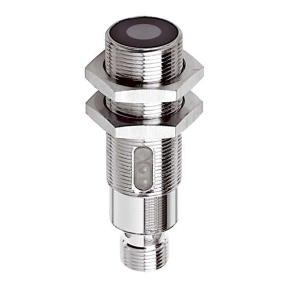
Zylindrische Bauformen
Die zylindrischen Bauformen verfügen
über eine kratzfeste Glasoptik und ein
stabiles Metallgehäuse. Eine LED am Gerät
zeigt die Funktionsreserve bei sicherem
Empfang an. Bei den Bauformen ∅ 4 mm
(mit Edelstahlgehäuse) und M5 durch eine
blinkende gelbe LED, bei den Bauformen
M12 und M18 durch eine grüne LED.
Die Tastweite ist bei den Bauformen M12
und M18 mit einem integrierten
Potentiometer einstellbar.
Serie OTV 22...
Die quaderförmige Miniaturbauform
OTV 22... hat ein stabiles Kunststoffge-
häuse. Die Funktionsreserve wird durch
eine grüne LED angezeigt. Die Einstellung
der Tastweite erfolgt über ein integriertes
Potentiometer.
Serie OTV 30...
Die Serie OTV 30... mit kratzfester
Glasoptik und stabilem Kunststoffgehäuse
kann mittels eines Montagewinkels
Authorized use
Diffuse reflective sensors are used as a
part of a higher-level overall system for
detection of objects.
conformity
EMV directive
Emitted interference
DIN EN 50081-1
Interference immunity
DIN EN 61000-6-2
Low voltage
73/23/EWG
directive
93/68/EWG
EN 61010
Safety instructions
Diffuse reflective sensors are not to be
used for safety applications, in particular
applications in which safety of persons
depends on proper operation of the
instruments.
The operator of the higher-level overall
system, e.g. a machine installation, is
responsible for complying with the
national and international safety and
accident prevention regulations which
apply to the specific use.
When carrying out machine planning and
using the diffuse reflective sensors, the
safety and accident prevention
regulations specific to use must be
complied with, e.g.:
- EN 60204, Electrical equipment of
machines
- EN 292, Safety of machines, general
principles of design
- DIN 57100 Teil 410, Protection against
dangerous electric shock
Assembly and electrical connection of
diffuse reflective sensors may only be
carried out by skilled personnel
according to applicable regulations in
de-energized condition and when the
machine is switched off. The
machine must be secured to ensure
that it cannot be switched back on.
Function
In case of diffuse reflective sensors,
transmitter and receiver are located in the
same housing. If an object enters the
detection zone of the sensor, the light
emitted by the transmitter is reflected by
the object. Part of the reflected light hits
on the receiver and so a change occurs in
the output status. The sensors are
available with red or infrared emitted light.
With red emitted light, alignment is easier
because of the visible light spot. A yellow
LED on the device indicates the output
status. Depending on the type, the output
function is either light-switching (NO, the
output is activated if an object reflects the
emitted light back to the receiver) or dark-
switching (NC, the output is activated if
no emitted light is reflected back to the
receiver).
Cylindrical Designs
The cylindrical designs possess scratch-
proof glass optics and a sturdy metal
housing. In case of secure reception the
function reserve is indicated via an LED.
With a flashing yellow LED at the designs
∅ 4 mm (with stainless steel housing) and
M5. With a green LED at the designs M12
and M18.
At the designs M12 and M18 the
detection range is set using an integrated
potentiometer.
Series OTV 22...
The cuboid miniature design OTV 22... has
a sturdy plastic housing. The function
reserve is displayed with a green LED.
The detection range is set using an
integrated potentiometer.
Series OTV 30...
The series OTV 30... with scratch-proof
glass optics and a sturdy plastic housing
can be fitted and aligned individually with
a mounting bracket.
individuell montiert und ausgerichtet
werden. Die Einstellung der Tastweite
erfolgt über ein integriertes 12-Gang-
Potentiometer.
Eine grüne LED am Gerät zeigt die
Funktionsreserve bei sicherem Empfang
an. Sie erlischt als Warnhinweis vor z.B.
Verschmutzung, Dejustage oder zu gering
eingestellter Sendeleistung.
Serie OTV 40...
Die Serie OTV 40... besitzt ein stabiles
Kunststoffgehäuse. Mittels eines Montage-
winkels werden die Geräte individuell
montiert und ausgerichtet. Mit einem
Drehschalter (immer auf Anschlag drehen)
wird die Ausgangsfunktion (NO/NC)
eingestellt . Die Einstellung der Tastweite
erfolgt über ein integriertes Potentiometer.
Serie OTV 60...
Die Serie OTV 60... mit stabilem
Aluminiumgehäuse besitzt einen
Prallschutz vor der Optik. Langlöcher im
Gehäuse und ein um 90° drehbarer,
genormter M12-Anschlussstecker
ermöglichen die individuelle Montage und
Ausrichtung der Geräte. Mit einem Dreh-
schalter (immer auf Anschlag drehen) wird
die Ausgangsfunktion (NO/NC) eingestellt.
Die Einstellung der Tastweite erfolgt über
ein integriertes Potentiometer.
Montage
Starke Fremdlichteinstrahlung auf den
Empfänger des Sensor vermeiden.
Zylindrische Bauformen
Montage über Klemmbock (∅ 4 mm) oder
das Gehäusegewinde.
Serie OTV 22... und Serie OTV 40...
Montage mit M3-Schrauben.
Serie OTV 30... und Serie OTV 60...
Montage mit M4-Schrauben.
Elektrischer Anschluß
Zylindrische Bauformen
Hellschaltend pnp über 3-polige
Anschlußkabel mit M12-Steckverbinder.
Dunkelschaltend pnp über 4-polige
Anschlußkabel mit M12-Steckverbinder.
Serie OTV 22...
Elektrischer Anschluss über fest
angeschlossene 3-polige Anschlußkabel.
Serie OTV 30... und Serie OTV 40...
Über 3-polige Anschlußkabel mit M8-
Steckverbinder.
Serie OTV 60...
Über 3-polige Anschlußkabel mit M12-
Steckverbinder.
Anschlußschema
BN
1
npn
BK
4
S
pnp
BU
3
BN = Braun/brown
BU = Blau/blue
BK = Schwarz/black
WH = Weiß/white
Ausrichten des Sensors
- Tastweite auf Maximum einstellen (nicht
Bauformen ∅ 4 mm und M5).
- Den Sensor auf das zu erkennende
Objekt ausrichten. Bei Rotlicht-Typen ist
der Lichtpunkt auf dem zu erkennenden
Objekt sichtbar. Der Ausgang muss jetzt
aktiv sein.
Einstellen der Tastweite
- Das zuerkennende Objekt im Erken-
nungsabstand vor dem Sensor
positionieren.
Serie OTV 12..., OTV 18..., OTV 22... und
OTV 30...
- Tastweite auf Minimum einstellen und
langsam erhöhen bis der Ausgang aktiv
wird.
- Tastweite weiter erhöhen, bis die
Funktionsreserve-LED aktiviert wird.
B 69/3.0102de
The detection range is set using an
integrated 12-turn potentiometer.
The function reserve is displayed with a
green LED, which serves as a warning
against, for instance, contamination,
disaglinment or low adjusted transmission
power.
Serie OTV 40...
The series OTV 40... possesses a sturdy
plastic housing. The devices are fitted and
aligned individually with a mounting
bracket. The output function (NO/NC) is
set with a selector switch (always turn to
end position).
The detection range is set using an
integrated potentiometer.
Serie OTV 60...
The series OTV 60... with a sturdy
aluminium housing possesses impact
protection in front of the optics. Oblong
holes in the housing and a standardized
M12 connector plug, which can be turned
90°, make it possible to fit and align the
devices individually. The output function
(NO/NC) is set by means of a selector
switch (always turn to end position).
The detection range is set using an
integrated potentiometer.
Assembly
Avoid exposing the receiver of the
Sensor to extraneous light.
Cylindrical designs
Mounting via clamping element (∅ 4 mm)
or the housing thread.
Series OTV 22... and series OTV 40...
Mounting with M3 screws.
Serie OTV 30... and series OTV 60...
Mounting with M4 screws.
Electrical connection
Cylindrical designs
Light-switching pnp via 3-core connecting
cable with M12 plug connector.
Dark-switching pnp via 4-core connecting
cable with M12 plug connector.
Series OTV 22...
Connection via a permanently connected
3-core connecting cable.
Series OTV 30... and series OTV 40...
Via 3-core connecting cable with M8 plug
connector.
Series OTV 60...
Via 3-core connecting cable with M12
plug connector.
Connection diagram
BN
1
BK
4
WH 2
pnp
BU
3
Nur zylindrische Bauformen M12/M18 mit Ausgang
pnp dunkelschaltend.
Cylindrical designs M12/M18 with dark-switching
pnp output only.
Aligning sensor
- Set operating distance to maximum (not
at designs ∅ 4 mm and M5).
- Align the sensor to the objekt that
should be detected. At red-light types
the light spot is visible on the object. The
output has to be active.
Adjustment of the operating distance
- Position the object to be detected in the
detection zone.
Series OTV 12..., OTV 18..., OTV 22...
and OTV 30...
- Set transmit power to minimum and
then increase the transmit power slowly
until the output changes to active.
- Increase the transmit power until the
function reserve LED lights up.
Advertisement

Related Manuals for Di-soric OTV Series


Summary of Contents for Di-soric OTV Series
- Page 1 Betriebsanleitung / Operating instructions Reflexions-Lichttaster / Diffuse reflective sensors B 69/3.0102de OTV... Bestimmungsgemäßer Gebrauch Authorized use individuell montiert und ausgerichtet The detection range is set using an werden. Die Einstellung der Tastweite integrated 12-turn potentiometer. Reflexions-Lichttaster werden als Bestand- Diffuse reflective sensors are used as a erfolgt über ein integriertes 12-Gang- The function reserve is displayed with a teil eines übergeordneten Gesamtsystems...
- Page 2 Tuch entfernen. Reparatur nur durch di- system of the sensor regularly with a soft das Potentiometer um ca. 20% vom potentiometer about approx. 20% of soric. cloth. Repair by di-soric only. Drehwinkel weiterdrehen. the rotation angle. Gewährleistung Warranty - Bei vorhandenem Hintergrund das - If there is a background remove the Es gelten die gesetzlichen Gewährleistungs-...