Advertisement
Quick Links
Installa on Instruc ons
for DesignRail
24VDC LED Ligh ng
®
Drivers are available in a variety of wa ages. In general a driver should not exceed more than 80% of its rated wa age.
(Example: 60W Driver = 60 x 0.8 = 48W Max).
Strip Lights require 1.44 wa s per foot. A er determining the necessary length of strip ligh ng, calculate the wa age and ensure the
driver being used has adequate capacity. (Example: 10' = 10 x 1.44 = 14.4W)
The maximum length of strip ligh ng that can be connected in one run is 25 feet. If one sec on of ligh ng is longer than 25 feet, it
must be broken into mul ple smaller sec ons and run on separate circuits.
Building codes vary by loca on and jurisdic on. Consult all applicable codes before installing DesignRail® LED Ligh ng.DesignRail®
LED Ligh ng may not be suitable for every applica on and it is the sole responsibility of the installer to ensure that DesignRail® LED
Ligh ng is used for its intended purpose.
WARNING: ELECTRIC SHOCK IS ALWAYS POSSIBLE WHEN WORKING WITH ELECTRICITY. THIS CAN CAUSE SERIOUS PERSONAL
INJURIES OR DEATH. ELECTRICAL SHORTS CAN ALSO CAUSE FIRES AND PROPERTY DAMAGE. ALWAYS MAKE SURE THE
ELECTRICAL OUTLET YOU ARE PLUGGING INTO IS GROUNDED.
1-800-888-2418 | www.feeneyinc.com
1
Advertisement

Related Manuals for Feeney DesignRail

Summary of Contents for Feeney DesignRail
- Page 1 Building codes vary by loca on and jurisdic on. Consult all applicable codes before installing DesignRail® LED Ligh ng.DesignRail® LED Ligh ng may not be suitable for every applica on and it is the sole responsibility of the installer to ensure that DesignRail® LED Ligh ng is used for its intended purpose.
-
Page 2: Package Contents
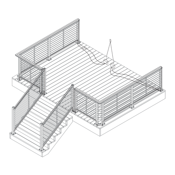
Power Kits - Package Contents POWER KIT OPTIONS SKU #7683 - 96w Power Kit 1x 96w Dimmable Driver 2x Mini Junc on Box 2x 11' Extension Cable 2x Wire Nuts (Pair) 2x Solder Connector COMMERCIAL GRADE ISOLATION WIRE NUTS WET LOCATION BUSHING (PAIR) 2x Isola on Bushing... - Page 3 Power Kits - Installa on Step 1 – Connect Source Power to Driver IMPORTANT SAFETY NOTE: TO REDUCE RISK OF ELECTRICAL SHOCK, TURN OFF AC CIRCUIT BREAKER PRIOR TO COMMENCING ANY ELECTRICAL WORK AND CONNECTING DRIVER(S) TO AC POWER SOURCE. VERIFY THAT LIVE POWER IS NOT PRESENT AT JUNCTION BOX WHEN MAKING CONNECTIONS. TOP RAIL LIGHTING - WIRING DIAGRAM Determine loca on of driver.
- Page 4 WIRE CAN BE RUN STEP 2 - DRILL POSTS AND ROUTE LEAD WIRE IN CONDUIT BURIED IN CONCRETE, OR RUN DIRECTLY FROM ENCLOSURE Note: Running the lead wire through the post is easier when done WIRE COMES TO POST. WIRE prior to moun ng post.
- Page 5 Use masking tape to temporarily secure lead wire(s) to outside of post to prevent retrac ng back into post. Post can now be mounted per DesignRail installa on instruc ons. Figure 1.6 SERIES 150...
- Page 6 PICKET base plate, and install picket sub-assembly panels. SERIES 200/300/350/450 (Standard DesignRail wih Horizontal Cable Steps Figure 2.1 11-13) For Series 200/300/350/450: measure the opening between the picket and post face on...
- Page 7 Step 2 - Install Strip Lights A ach female connector of light strip to male connector of top rail lead wire (See Figure 2.5). Remove adhesive strip cover and discard. Insert light strip into isert channel, while feeding lead wire back into post and rou ng opposite end connector up and over intermediate picket.
- Page 8 Step 3 - Install Diff user Lens Measure the opening between the picket and post face on each side of the picket . These dimensions should be MEASURE MEASURE (See Figure 2.8) equal. Cut diff user lens to length to fi t on each side of the picket, using Figure 2.8 a sharp u lity knife, or heavy duty u lity scissors/shears.
- Page 9 Light Kits - Bo om Rail Installa on Step 1 - Prepare Railing Frame Measure opening between the post faces beneath the bo om rail (See Figure 3.1) Cut channeled bo om rail inert to fi t between posts. Trim channel por on of isert at both ends to clear RCBs. This can be done by cu ng the ‘top’...
- Page 10 Step 2 - Install Strip Lights A ach female connector of light strip to male connector of top rail lead wire . If necessary a ach addi onal light (See Figure 3.4) strips to male connector to fi ll en re length of bo om rail channel Remove adhesive strip cover and discard.
- Page 11 48” lens, then trim the second lens to fi t the remainder of the opening. Insert diff user lens into bo om rail infi ll, as shown (See Figure 3.8). Figure 3.8 ©2018 Feeney Inc. AF#2018-1503 1-800-888-2418 | www.feeneyinc.com...
Need help?
Do you have a question about the DesignRail and is the answer not in the manual?
Questions and answers