Table of Contents
Advertisement
Quick Links
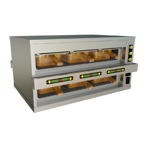
INFRARED
HEATSINK™
HOLDING UNIT
Includes Standalone,
Kitchen Minder and
VISOR models
MODELS
IRHS22
IRHS23
IRHS24
IRHS34
IRHS42
Please read this manual completely before attempting
This document is prepared for trained Duke service technicians. It is not to be used by anyone not properly
qualified to perform these procedures.
This Service Manual is not all encompassing. If you have not been trained on servicing this product, be sure
to read the manual completely before attempting servicing. Be sure all necessary tools, test equipment,
and skills are available. Those procedures for which you do not have the proper skills and test equipment
must be performed only by a qualified Duke trained service technician.
This manual is Copyright © 2015 Duke Manufacturing Co. All rights reserved.
Reproduction without written permission is prohibited. Duke is a registered trademark of the Duke Manufacturing Co.
Phone: 314-231-1130 • Toll Free: 1-800-735-3853 • Fax: 314-231-5074
service-dispatch@dukemfg.com • www.dukemfg.com
SM-PH-IH-0003
to install, operate or service this equipment.
Duke Manufacturing Co.
2305 North Broadway • St. Louis, MO 63102-1405
Service Manual
11/18/2015
Advertisement
Table of Contents
Troubleshooting

Subscribe to Our Youtube Channel
Related Manuals for Duke Infrared Heatsink


Summary of Contents for Duke Infrared Heatsink
- Page 1 Please read this manual completely before attempting to install, operate or service this equipment. This document is prepared for trained Duke service technicians. It is not to be used by anyone not properly qualified to perform these procedures. This Service Manual is not all encompassing. If you have not been trained on servicing this product, be sure to read the manual completely before attempting servicing.
- Page 2 Infrared HeatSink (IRHS) Holding Unit Service Manual IMPORTANT WARNING AND SAFETY INFORMATION READ THIS MANUAL THOROUGHLY BEFORE OPERATING, INSTALLING OR PERFORMING MAINTENANCE ON THE EQUIPMENT. READ THIS MANUAL THOROUGHLY BEFORE OPERATING, INSTALLING OR PERFORMING MAINTENANCE ON THE EQUIPMENT FAILURE TO FOLLOW INSTRUCTIONS IN THIS MANUAL CAN CAUSE PROPERTY DAMAGE, INJURY OR DEATH.
-
Page 3: Table Of Contents
Infrared HeatSink (IRHS) Holding Unit Service Manual TABLE OF CONTENTS SPECIFICATIONS ............................5 IRHS22 .............................. 5 IRHS23 .............................. 6 IRHS24 .............................. 7 IRHS34 .............................. 8 IRHS42 .............................. 9 REMOVAL AND REPLACEMENT OF PARTS ....................10 EQUIPMENT USED IN THESE INSTRUCTIONS ...................10 ELECTRICAL LOCKOUT/TAGOUT PROCEDURE...................10 ESD WRIST STRAP..........................11 DECK ASSEMBLY COMPONENTS .......................12 MENU BA RS ..........................12 KEYPAD DISPLAYS ........................14 RTD (TEMPERATURE) SENSORS ....................16... - Page 4 Infrared HeatSink (IRHS) Holding Unit Service Manual TROUBLESHOOTING & DIAGNOSTICS .....................42 IRHS TROUBLESHOOTING FLOW CHART ..................42 IRHS TROUBLESHOOTING GUIDE .....................43 IRHS COMPONENT TECHNICAL SPECIFICATIONS ................44 OPERATIONS ............................47 OPERATING PROCEDURES ........................ 47 OPERATIONS ..........................47 Changing Dayparts ......................48 Display Link, Hold Time, or Temperature ................49 DIAGNOSTICS ..........................50 Checking Heat Sink Temperature ..................50 Checking IR Bulb Function ....................50 Checking Product Settings (via USB file) ................50 Error Codes ......................... 51 Temperature Check Procedure ...................51 CLEANING & ROUTINE MAINTENANCE ....................52 CLEANING ............................52 RECOMMENDED SUPPLIES.......................52...
-
Page 5: Specifications
Infrared HeatSink (IRHS) Holding Unit Service Manual SPECIFICATIONS IRHS22 Before Serial# 10140480 As of Serial# 10140480 (10/1/14) Shipping Weight 125 lbs / 56.7 kg 110 lbs / 49.9 kg Model Electrical Plug IRHS22-208 208V ~ 12 A, 50/60 Hz NEMA 6-15P SHUKO, 16 AMP 14.4 in / 19.3 in / 20.1 in / 13.3 in / 19.3 in / 20.1 in / IRHS22-230 230V ~ 12 A, 50/60 Hz 36.6 cm... -
Page 6: Irhs23
Infrared HeatSink (IRHS) Holding Unit Service Manual IRHS23 Up to Serial# 101413198 After SN# 101413198 (10/20/14) Shipping Weight 160 lbs / 72.6 kg 143 lbs / 64.9 kg Model Electrical Plug IRHS23-208 208V ~ 12 A, 50/60 Hz NEMA 6-15P SHUKO, 16 AMP 14.4 in / 26.4 in / 20.1 in / 13.3 in / 26.4 in / 20.1 in / IRHS23-230 230V ~ 12 A, 50/60 Hz 36.6 cm... -
Page 7: Irhs24
Infrared HeatSink (IRHS) Holding Unit Service Manual IRHS24 Before Serial# 10140545 As of Serial# 10140545 (10/3/14) Shipping Weight 195 lbs / 88.4 kg 181 lbs / 82.1 kg Model Electrical Plug IRHS24-208 208V ~ 12 A, 50/60 Hz NEMA 6-15P SHUKO, 16 AMP 14.4 in / 33.4 in / 20.1 in / 13.3 in / 33.4 in / 20.1 in / IRHS24-230 230V ~ 12 A, 50/60 Hz 36.6 cm... -
Page 8: Irhs34
Infrared HeatSink (IRHS) Holding Unit Service Manual IRHS34 Before Serial# 10140032 As of Serial# 10140032 (10/1/14) Shipping Weight 275 lbs / 124.7 kg 243 lbs / 110.2 kg Model Electrical Plug IRHS34-208 208V ~ 16 A, 50/60 Hz NEMA 6-20P SHUKO, 16 AMP 20.9 in / 33.4 in / 20.1 in / 19.3 in / 33.4 in / 20.1 in / IRHS34-230 230V ~ 16 A, 50/60 Hz 53.1 cm... -
Page 9: Irhs42
Infrared HeatSink (IRHS) Holding Unit Service Manual IRHS42 Shipping Weight 187 lbs / 84.8 kg Model Electrical Plug IRHS42-208 208V ~ 12 A, 50/60 Hz NEMA 6-15P SHUKO, 16 AMP 25.3 in / 19.3 in / 20.1 in / IRHS42-230 230V ~ 12 A, 50/60 Hz 64.3 cm 49.0 cm 51.1 cm (as of 11/3/14) IEC, 16 AMP IRHS42-240... -
Page 10: Removal And Replacement Of Parts
Infrared HeatSink (IRHS) Holding Unit Service Manual REMOVAL AND REPLACEMENT OF PARTS EQUIPMENT USED IN THESE INSTRUCTIONS ELECTRICAL LOCKOUT/TAGOUT PROCEDURE • Phillips screwdriver • #1 precision screwdriver WARNING • Flat-head screwdriver BEFORE PERFORMING ANY SERVICE THAT INVOLVES ELECTRICAL CONNECTION OR • Needle-nose pliers DISCONNECTION AND/OR ExPOSURE TO ELECTRICAL COMPONENTS, ALWAYS • 11/16" open-end wrench... -
Page 11: Esd Wrist Strap
Infrared HeatSink (IRHS) Holding Unit Service Manual ESD WRIST STRAP Electrostatic Discharge (ESD) is one of the biggest dangers to components in electronic devices. An ESD wrist strap allows any accumulated static charge to disperse safely through its cable, rather than through static-sensitive components such as unit computer- related components. 1. Place the ESD wrist strap around your wrist. The wrist strap should be next to your skin, so it needs to be placed under any clothes. 2. Tighten the wrist strap so that the attached metal plate maintains good contact with your skin. Do not over tighten as the wrist strap should not be uncomfortable. 3. Connect the cable to the wrist strap if it is disconnected. The cable should be securely clipped... -
Page 12: Deck Assembly Components
Infrared HeatSink (IRHS) Holding Unit Service Manual DECK ASSEMBLY COMPONENTS 4. Mark and disconnect the affected Menu Bar’s MENU BA RS molex connector inside the control compartment. The Menu Bars hold the Keypad Displays that control 5. If it is necessary to reuse the existing Keypad and monitor the performance of each heating well. The Displays in a replacement Menu Bar: quantity varies (depending on model) and are located on the front and back faces of the unit. a. Remove and retain the two (2) screws securing the Menu Bar Back Channel and pry out of the TOOLS REQUIRED: Phillips screwdriver;... - Page 13 Infrared HeatSink (IRHS) Holding Unit Service Manual c. Disconnect the affected Keypad Display(s) RESTORE electrical connector from the Menu Bar 6. Carefully place the Keypad Displays in place on Harness. the interior side of the replacement Menu Bar. If d. The Keypad Displays are attached to the Menu reusing the Keypad Displays, it may be necessary Bar with double-sided glue dots. Carefully pry to use additional double-sided tape to secure the off and remove the affected Keypad Display Keypad Displays to the Menu Bar. from the Menu Bar. e. Carefully scrape any remaining adhesive residue from the inside of the Menu Bar.
-
Page 14: Keypad Displays
Infrared HeatSink (IRHS) Holding Unit Service Manual 5. Remove and retain the screws securing the Menu KEYPAD DISPLAYS Bar Back Channel from the front of the Menu Bar and pry out of the Menu Bar. The Keypad Displays control and monitor the performance of each heating well. They are located inside of the Menu Bar(s) and the quantity varies (depending on model). TOOLS REQUIRED: Phillips screwdriver; Flat-head screwdriver 1. Place the unit’s Power Switch in the OFF position... - Page 15 Infrared HeatSink (IRHS) Holding Unit Service Manual 7. Disconnect the affected Keypad Display(s) RESTORE: electrical connector from the Menu Bar Harness. 10. Peel off the adhesive cover from the glue dots and 8. The Keypad Displays are attached to the Menu place on the replacement Keypad Display. Bar with double-sided glue dots. Carefully pry off and remove the affected Keypad Display from the Menu Bar. 9. Carefully scrape any remaining adhesive residue 11. Peel off the other adhesive cover from the glue from the inside of the Menu Bar.
-
Page 16: Rtd (Temperature) Sensors
Infrared HeatSink (IRHS) Holding Unit Service Manual 4. Remove and retain the screws securing the Control RTD (TEMPERATURE) SENSORS Side Cover and remove the cover. The RTD Sensors monitor the temperature of the heating wells. They are affixed to the bottom-center of each Heat Element, and the quantity varies (depending on model). TOOLS REQUIRED: Phillips screwdriver; Aluminum tape; Tie wraps 1. Place the unit’s Power Switch in the OFF position and follow the proper Lockout/Tagout procedures. 2. Remove any pans and covers on the level(s) being removed. NOTE: If the RTD Sensor to be replaced is on a lower... - Page 17 Infrared HeatSink (IRHS) Holding Unit Service Manual 7. Remove the four (4) screws (2 in front, 2 in back) 9. Invert the liner deck assembly upside-down, then securing the liner deck assembly to the unit. remove and retain the insulation. 10. The RTD Sensor is attached to the heat element with double-sided adhesive tape and covered with aluminum tape. Carefully pry off and remove the affected RTD Sensor from the Heat Element. 8. Carefully lift the entire liner deck assembly out through the top of the unit. This may require two people, depending on the location of the IRHS unit. Though not required to do so, removing the level’s IR glass frame assembly (instructions are contained in the Emitter instructions) will lighten RESTORE: the weight of the liner deck assembly and make 11. Peel off the adhesive tape cover from the...
-
Page 18: High Limit Thermostats
Infrared HeatSink (IRHS) Holding Unit Service Manual 13. Invert the liner deck assembly right-side up. HIGH LIMIT THERMOSTATS While feeding the RTD Sensor, Emitter, and Heat Element wires through the appropriate control The High Limit Thermostats monitor well temperatures compartment bushings, carefully slide the liner and serves as an emergency circuit interrupter in case deck assembly into the unit, taking caution not of inadvertent overheating. There is one per level, and to damage any of the wires. are affixed to the bottom-center of each heat sink. NOTE: This may require two people, depending on TOOLS REQUIRED: Phillips screwdriver;... - Page 19 Infrared HeatSink (IRHS) Holding Unit Service Manual 4. Remove and retain the screws securing the Control 7. Remove the four (4) screws (2 in front, 2 in back) Side Cover and remove the cover. securing the liner deck assembly to the unit. NOTE: If the High Limit Thermostat to be replaced is on a lower level, start from the top and repeat the following four steps for each level above the desired level.
- Page 20 Infrared HeatSink (IRHS) Holding Unit Service Manual 9. Invert the liner deck assembly upside-down, then 14. Install the replacement High Limit Thermostat and remove and retain the insulation. secure with its nuts. 10. Mark and disconnect the spade terminals for the 15. Reattach the High Limit Thermostat spade affected High Limit Thermostat. terminals. Be sure to reapply the tape that helps secure the spade terminals to the High Limit Thermostat. 11. Remove and retain the two (2) 11/32" nuts securing the High Limit Thermostat to the heat sink and remove the High Limit Thermostat. 16. Feed the Heat Element and RTD Sensor wires in the direction of and through the control compartment bushings and replace the insulation.
-
Page 21: Heat Elements
Infrared HeatSink (IRHS) Holding Unit Service Manual 4. Remove and retain the screws securing the Control HEAT ELEMENTS Side Cover and remove the cover. The Heat Elements provide the heating required to keep NOTE: If the Heat Element to be replaced is on a the heating wells at proper operating temperatures. lower level, start from the top and repeat the The quantity varies depending on model and are affixed following four steps for each level above the to the bottom of each Heat Sink. - Page 22 Infrared HeatSink (IRHS) Holding Unit Service Manual 7. Remove the four (4) screws (2 in front, 2 in back) 11. Remove and retain the two (2) 11/32" nuts securing securing the liner deck assembly to the unit. the High Limit Thermostat to the heat sink and remove the High Limit Thermostat. 12. Clean the mounting surface of any residual heat transfer compound. 8. Carefully lift the entire liner deck assembly out through the top of the unit. This may require two people, depending on the location of the IRHS unit. Though not required to do so, removing the level’s IR glass frame assembly (instructions are contained in the Emitter instructions) will lighten 13. Remove the affected Heat Element by peeling off the weight of the liner deck assembly and make from the heat sink. Ensure any excess tape and/...
- Page 23 Infrared HeatSink (IRHS) Holding Unit Service Manual 14. Peel the adhesive tape cover off the replacement 18. Feed the Heat Element and RTD Sensor wires in the Heat Element and press in place on the heat sink, direction of and through the control compartment ensuring all air bubbles are smoothed out. bushings and replace the insulation. 19. Invert the liner deck assembly right-side up. While feeding the RTD Sensor, Emitter, and Heat Element wires through the appropriate control compartment bushings, carefully slide the liner deck assembly into the unit, taking caution not to damage any of the wires.
-
Page 24: Emitter (Ir Bulb) Sockets
Infrared HeatSink (IRHS) Holding Unit Service Manual a. Remove and retain the screws securing the EMITTER (IR BULB) SOCKETS appropriate Menu Bar(s) and move to one side. It is not necessary, but recommended, The Emitter Sockets hold and provide power to the to completely remove the Menu Bar from the Emitters. There are two (2: 1 front, 1 back) at the top unit. Menu Bar instructions are contained in of each heating well. this manual. TOOLS REQUIRED: Phillips screwdriver; clean gloves/ cloths/towels; 11/16" open-end wrench; Tie wraps 1. Place the unit’s Power Switch in the OFF position and follow the proper Lockout/Tagout procedures. - Page 25 Infrared HeatSink (IRHS) Holding Unit Service Manual d. Remove the four (4) screws (2 in front, 2 in You will now have access to remove the nut securing back) securing the liner deck assembly to the socket in place. unit. 5. Each liner deck’s frame support angles (front and back) support the IR glass frame assembly in place. Remove and retain the screws securing the frame support angle on the row where the affected Socket is to be replaced and remove the frame support angle. Repeat for the other side of the liner deck assembly. Be careful to support and not let the IR glass frame assembly fall and damage the heat sink. e. Carefully lift the entire liner deck assembly out through t he t op o f t he u nit. T his m ay r equire t wo people, depending on the location of the IRHS unit. Though not required to do so, removing...
- Page 26 Infrared HeatSink (IRHS) Holding Unit Service Manual RESTORE: 11. Install the replacement Emitter Socket into its mounting hole and secure with its nut. 12. Using clean gloves, a clean cloth, or a clean paper towel, reinstall or insert the replacement Emitter into the rear socket first and then gently push inward until the front of the bulb can be inserted into the front socket. 13. Slide the IR glass frame assembly into the liner deck assembly.
-
Page 27: Emitters (Ir Bulbs)
Infrared HeatSink (IRHS) Holding Unit Service Manual EMITTERS (IR BULBS) The Emitters heat the top of each well. The quantity varies (depending on model) and are held in place by two Emitter Sockets at the top of each heating well. TOOLS REQUIRED: Phillips screwdriver; clean gloves/ cloths/towels; Tie wraps 6. The Emitter Sockets are spring-loaded. Push the 1. Place the unit’s Power Switch in the OFF position Emitter towards the rear socket until the Emitter and follow the proper Lockout/Tagout procedures. is free from the front socket and carefully remove. 2. Remove all pans and covers from the liner deck NOTE: DO NOT TOUCH THE EMITTER WITH BARE assembly where the affected Emitter is to be HANDS! The oil on human skin will shorten replaced. -
Page 28: Control Compartment Components - Standalone & Kitchen Minder Models (Only)
Infrared HeatSink (IRHS) Holding Unit Service Manual CONTROL COMPARTMENT COMPONENTS – STANDALONE & KITCHEN MINDER MODELS (ONLy) POWER SWITCH USB ADAPTER The Power Switch is located The USB Adapter is used on the Control Panel on to program the Controller the face of the unit. It is... -
Page 29: Daypart Switch
Infrared HeatSink (IRHS) Holding Unit Service Manual DAYPART SWITCH RELAYS (Smart Power Modules) The Daypart Switch is used The Relays control the Emitters (IR Bulbs) and Heat to control the temperatures Elements. Each unit has several (depending on model) of various food products, and are located inside the control compartment. up to three different time periods a day. It is located... -
Page 30: Controller
Infrared HeatSink (IRHS) Holding Unit Service Manual CONTROLLER TRANSFORMER The Controller is used to control the Relays and RTD The Transformer is used to step-down power to 12 Sensors. It is located inside the control compartment. VAC for the Controller. It is located inside the control compartment. TOOLS REQUIRED: Phillips screwdriver; #1 precision screwdriver TOOLS REQUIRED: Phillips screwdriver 1. Place the unit’s Power Switch in the OFF position 1. Place the unit’s Power Switch in the OFF position and follow the proper Lockout/Tagout procedures. and follow the proper Lockout/Tagout procedures. 2. Remove and retain the screws securing the Control 2. Remove and retain the screws securing the Control... -
Page 31: Rtd Board
Infrared HeatSink (IRHS) Holding Unit Service Manual RESTORE: RTD BOARD 6. Wearing the ESD Wrist Strap, and following ESD The RTD Board controls the RTD Sensors. It is located procedures, install the replacement RTD Board inside the control compartment. and secure with its screws. TOOLS REQUIRED: Phillips screwdriver; ESD strap; 1/4" 7. Reconnect the RTD Board wires and plug. nut driver or socket 8. Replace the Control Side Cover and secure with 1. Place the unit’s Power Switch in the OFF position its screws. and follow the proper Lockout/Tagout procedures. -
Page 32: Fuses And Fuse Holder
Infrared HeatSink (IRHS) Holding Unit Service Manual FOR FUSE HOLDER REPLACEMENT: FUSES AND FUSE HOLDER 1. Place the unit’s Power Switch in the OFF position The Fuses and Fuse Holder serve as a circuit interrupter and follow the proper Lockout/Tagout procedures. from the main power input. They are located inside the control compartment. 2. Remove and retain the screws securing the Control Side Cover and remove the cover. TOOLS REQUIRED: Phillips screwdriver 3. Disconnect the spade connectors connected to 1. Place the unit’s Power Switch in the OFF position the Fuse Holder. and follow the proper Lockout/Tagout procedures. 4. Remove and retain the screws securing the Fuse 2. Remove and retain the screws securing the Control... -
Page 33: Control Compartment Components - Kitchen Minder Model (Only)
Infrared HeatSink (IRHS) Holding Unit Service Manual CONTROL COMPARTMENT COMPONENTS – KITCHEN MINDER MODEL (ONLy) NOTE: The following components are installed, in addition to all previously listed control compartment components, in the Kitchen Minder model of the IRHS. NOTE: THE USE OF AN ESD WRIST STRAP IS STRONGLY RECOMMENDED. -
Page 34: Kitchen Minder Adapter Board (If Installed)
Infrared HeatSink (IRHS) Holding Unit Service Manual NOTE: THE USE OF AN ESD WRIST STRAP IS STRONGLY RECOMMENDED. FOLLOW ESD PROCEDURES ON PAGE 11. RESTORE: KITCHEN MINDER ADAPTER BOARD (if installed) 6. Wearing the ESD Wrist Strap, and following ESD If Kitchen Minder is installed in the unit, the Kitchen... -
Page 35: Mounting Plate (If Installed)
Infrared HeatSink (IRHS) Holding Unit Service Manual 5. Remove and retain the four (4) screws securing the MOUNTING PLATE (if installed) Mounting Plate to the rear control panel. If Kitchen Minder is installed in the unit, the Mounting Plate is located in the rear control panel. The Mounting Plate holds the Couplers. The type depends on the specific model: Domestic (2-Hole) and CE (2-Hole or 3-Hole). RESTORE: 6. Install the replacement Mounting Plate in the rear control panel and secure with its screws. 7. If necessary, reinstall the Couplers into the TOOLS REQUIRED: Phillips screwdriver Mounting Plate with their screws. -
Page 36: Couplers (If Installed)
Infrared HeatSink (IRHS) Holding Unit Service Manual RESTORE: COUPLERS (if installed) 5. Insert the replacement Coupler(s) and attach with If Kitchen Minder is installed in the unit, the Couplers its screws. are located in the Mounting Plate on the rear Control Panel. Couplers are the connection point between the 6. Reconnect the Coupler line(s). Master and Satellite Kitchen Minder units allowing 7. Replace the Control Side Cover and secure with them to be connected and communicate. The quantity its screws. varies depending on the specific model – two (2; one RJ45 and one RJ12) in the Domestic model or three 8. Restore power to the unit and test for proper (3; all CAT5/RJ45) in the CE model. -
Page 37: Control Compartment Components - Visor Model (Only)
Infrared HeatSink (IRHS) Holding Unit Service Manual CONTROL COMPARTMENT COMPONENTS – VISOR MODEL (ONLy) NOTE: All previously listed control compartment components (Standalone and Kitchen Minder models) are NOT INSTALLED in the VISOR models of the IRHS. NOTE: THE USE OF AN ESD WRIST STRAP IS STRONGLY RECOMMENDED. -
Page 38: Power Control Board - Acm
Infrared HeatSink (IRHS) Holding Unit Service Manual NOTE: THE USE OF AN ESD WRIST STRAP IS STRONGLY RECOMMENDED. FOLLOW ESD PROCEDURES ON PAGE 11. RESTORE: POWER CONTROL BOARD – ACM 6. Wearing the ESD Wrist Strap, and following ESD If VISOR is installed in the unit, the ACM Power Control procedures, install the replacement ACM Power Board is located on the VISOR Control Panel inside the Control Board onto its nylon PC lock-in supports control compartment. and secure in place with its nut. 7. Reconnect the spade and molex connectors. -
Page 39: Power Control Board - 103M
Infrared HeatSink (IRHS) Holding Unit Service Manual NOTE: THE USE OF AN ESD WRIST STRAP IS STRONGLY RECOMMENDED. FOLLOW ESD PROCEDURES ON PAGE 11. 5. Squeeze each of the three (3) nylon PC lock-in POWER CONTROL BOARD – 103M supports with needle-nose pliers to release the 103M Power Control Board off of the control panel. -
Page 40: Power Control Board - Triac Drive
Infrared HeatSink (IRHS) Holding Unit Service Manual NOTE: THE USE OF AN ESD WRIST STRAP IS STRONGLY RECOMMENDED. FOLLOW ESD PROCEDURES ON PAGE 11. RESTORE: POWER CONTROL BOARD – TRIAC DRIVE 6. Wearing the ESD Wrist Strap, and following ESD If VISOR is installed in the unit, the Triac Drive Power procedures, install the replacement Triac Drive... -
Page 41: Fuse Holder And Fuses
Infrared HeatSink (IRHS) Holding Unit Service Manual RESTORE: FUSE HOLDER AND FUSES 5. Install the replacement Fuse Holder and secure The Fuses and Fuse Holder serve as a circuit interrupter with its screws. from the main power input. They are located on the VISOR Control Panel, inside the control compartment. 6. Reconnect the spade connectors. 7. INSTALL CORRECTLY RATED FUSES ONLY! NOTE: Replacing fuse(s) with an incorrect rating can cause nuisance blowing if rating is too low, or a loss of circuit protection if too high. Damage to the equipment and risk of fire may result. -
Page 42: Troubleshooting & Diagnostics
Infrared HeatSink (IRHS) Holding Unit Service Manual TROUBLESHOOTING & DIAGNOSTICS IRHS TROUBLESHOOTING FLOW CHART SM-PH-IH-0003 11/18/2015... -
Page 43: Irhs Troubleshooting Guide
Infrared HeatSink (IRHS) Holding Unit Service Manual IRHS TROUBLESHOOTING GUIDE COMPONENT CHECK STATE POSSIBLE CONDITIONS SOLUTION(S) Unplugged Plug Power Cord into correct receptacle Power Cord damaged Repair/Replace Power Cord Circuit Breaker tripped Reset panel breaker Unit Powered? Faulty receptacle Replace receptacle Fuse Replace Fuse Wiring/Connectors Trace and repair wiring On/Off Switch Replace On/Off Switch Transformer Replace Transformer Controller Replace Controller Both Bars Keypad Display Replace Keypad Display Wiring/Connectors Trace and repair wiring... -
Page 44: Irhs Component Technical Specifications
Infrared HeatSink (IRHS) Holding Unit Service Manual IRHS COMPONENT TECHNICAL SPECIFICATIONS PART NO. DESCRIPTION SPECIFICATIONS ACM, Power Control Board 166112 (VISOR-only) 166080 Controller; Renau HMC-34 166017 Emitter, IRHS; 208 VAC • 208 VAC; 340 (170 x 2) W (± 3%) 166018 Emitter, IRHS; 240 VAC • 240 VAC; 340 (170 x 2) W (± 3%) 166004 Heat Element; 2-Wide, 208 VAC • 208 VAC; 300 W 166005 Heat Element; 2-Wide, 240 VAC • 240 VAC; 300 W 166007 Heat Element; 3-Wide, 208 VAC • 208 VAC; 450 W... - Page 45 Infrared HeatSink (IRHS) Holding Unit Service Manual PART NO. DESCRIPTION SPECIFICATIONS • Input: 5 VDC Keypad Display; Up/Down 166082 • Pins: (all configurations) — Pin #1: GND — Pin #2: 5 VDC Keypad Display; Up/Up 166083 — Pin #3: Data In (only with 3x4 configurations) — Pin #4: Data Out • 1.5 A; 125 VDC • Torque: 12 Kgf/cm 166111 Modular Jack (VISOR-only) • CAT 5 • IP67 • Primary 208/230 VAC; Secondary: 12 VAC Power Control Board 120011 (VISOR-only) • Max. Load Current: 20 Arms. Heat sinking required.
- Page 46 Infrared HeatSink (IRHS) Holding Unit Service Manual PART NO. DESCRIPTION SPECIFICATIONS 158279 RTD Sensor • Temperature Range: -65°F to 260°F 158312 Thermostat, High Limit • Opens @ 300°F; Closes @ 270°F • Primary: 208/240 VAC; Secondary: 12 VAC Transformer; 208/240 VAC 155749 • Input: 230 VAC; 50/60 Hz; Output: 12.6 V @ 2.38 A 156838 Transformer; 230 VAC SM-PH-IH-0003 11/18/2015...
-
Page 47: Operations
Infrared HeatSink (IRHS) Holding Unit Service Manual OPERATIONS OPERATING PROCEDURES 2. Arrow Buttons: • Ensure proper pan covers are inserted into the a. Used for starting/stopping/resetting the correct location for broiled products. menu. • Upon turning ON, allow the unit to heat until the b. Used to access Menu Mode. menu bars display the pre-programmed product c. Indicate which pan the adjacent status LED names. This does not occur before reaching proper... -
Page 48: Changing Dayparts
Infrared HeatSink (IRHS) Holding Unit Service Manual c. After selecting the UP or DOWN Arrow, press Changing Dayparts the ENTER Button “ ” to accept. There are two methods for selecting Dayparts: d. Status LED stops flashing and “MEAL SET1” appears on the Display. 1. Select the appropriate Daypart Button to switch between breakfast, lunch, and dinner menus. If necessary, the three (3) parts can be programmed for any three separate time periods – not just “breakfast”, “lunch”, and/or “dinner” menus. e. Press the ENTER button again. Status LED flashes indicating Menu Mode. -
Page 49: Display Link, Hold Time, Or Temperature
Infrared HeatSink (IRHS) Holding Unit Service Manual 6. Press the UP arrow button repeatedly to scroll Display Link, Hold Time, or Temperature up or down through “LINK”, “TIME”, and “TEMP”. The DOWN arrow button can be used to cycle the 1. Enter Menu Mode by pressing and holding the opposite direction. ENTER button “ ” for three (3) seconds. 2. Status LED flashes, “MENU” is displayed on left Display, and either “UP” or “DOWN” is displayed on the right display – indicating which pan location information will be displayed/controlled. -
Page 50: Diagnostics
Infrared HeatSink (IRHS) Holding Unit Service Manual DIAGNOSTICS Checking Heat Sink Temperature Checking Product Settings (via USB file) • A surface temperature probe can be used to check 1. Turn the IRHS on and wait for temperature or the temperature of the heat sink surface. product names to display. • No pans should be in wells during the pre-heat and 2. Insert a blank USB drive (any size) into the USB temperature check period. Pre-heat the holding port. The USB port LED will light solid green and unit for 30 minutes before taking any temperature a single chirp should be heard. -
Page 51: Error Codes
Infrared HeatSink (IRHS) Holding Unit Service Manual Error Codes Temperature Check Procedure The RTD Board performs a routine, internal check 1. No pans should be in wells during the pre-heat and temperature check. Pre-heat the warmer after turning the unit on to validate the unit is sensing temperature and heating properly. In the event of a... -
Page 52: Cleaning & Routine Maintenance
Infrared HeatSink (IRHS) Holding Unit Service Manual CLEANING & ROUTINE MAINTENANCE CLEANING IF DAILY CLEANING IS PERFORMED ROUTINELY, DEEPER, MORE AGGRESSIVE, CLEANING METHODS CAN BE AVOIDED. OVER LONGER PERIODS OF TIME, FRIED RECOMMENDED SUPPLIES FOOD PRODUCTS CAN ACCUMULATE AND BAKE ON SURFACES OF THE COMPARTMENTS. • Cleaning Towels Cleaning solutions need to be alkaline based or non- • Non-Scratch Scrub Pad... -
Page 53: Daily Cleaning Procedures
Infrared HeatSink (IRHS) Holding Unit Service Manual 5. Fully clean upper glass surfaces by hand. Spray a DAILY CLEANING PROCEDURES cleaning towel, or non-scratch scrub pad when necessary, with soapy solution degreaser. Never use a high-pressure water wash for this cleaning procedure as water can damage electrical components. NOTE: Never spray cleaning solution directly onto the cabinet. 1. Turn unit off, unplug, and allow to cool for at least 10 minutes. 6. Use sanitizer-soaked towels to wipe out all interior compartments on the unit. Wipe the top 2. Remove all holding pans and covers. Wash, rinse, compartments first, then the remaining levels from and sanitize at the 3-compartment sink. -
Page 54: Website Programming
Infrared HeatSink (IRHS) Holding Unit Service Manual WEBSITE PROGRAMMING Log on. www.dukemfg.info/bkirhs User Name: manager Password: password (case sensitive) NOTE: When you first log onto this page, you must: 1) Select the desired equipment configuration on the left, before it will… 2) …show up on the right side in order to be programmed. 3) If necessary, change the Cabinet Temperature Unit to “°C” (Celsius) - Page 55 Infrared HeatSink (IRHS) Holding Unit Service Manual SM-PH-IH-0003 11/18/2015...
- Page 56 Infrared HeatSink (IRHS) Holding Unit Service Manual SM-PH-IH-0003 11/18/2015...
- Page 57 Infrared HeatSink (IRHS) Holding Unit Service Manual Unit Programming Instructions 1) Power off the unit. 2) Insert the flash drive into the USB slot. 3) Power on the unit. 4) The program will automatically be installed. The unit will chirp a few times, the Emitters will cycle, and the display shows different displays while programming is in progress...
-
Page 58: Wiring Schematics
Infrared HeatSink (IRHS) Holding Unit Service Manual WIRING SCHEMATICS IRHS DECK WIRING SM-PH-IH-0003 11/18/2015... -
Page 59: Irhs22 Wiring Diagram
Infrared HeatSink (IRHS) Holding Unit Service Manual SM-PH-IH-0003 11/18/2015... -
Page 60: Irhs23 Wiring Diagram
Infrared HeatSink (IRHS) Holding Unit Service Manual CONNECT SM-PH-IH-0003 11/18/2015... -
Page 61: Irhs24 Wiring Diagram
Infrared HeatSink (IRHS) Holding Unit Service Manual 208V 230V SM-PH-IH-0003 11/18/2015... -
Page 62: Irhs34 Wiring Diagram
Infrared HeatSink (IRHS) Holding Unit Service Manual SM-PH-IH-0003 11/18/2015... -
Page 63: Irhs42 Wiring Diagram
Infrared HeatSink (IRHS) Holding Unit Service Manual ” 208V 230V SM-PH-IH-0003 11/18/2015... -
Page 64: Visor Interface Cable Wiring Diagram
Infrared HeatSink (IRHS) Holding Unit Service Manual OUT4 OUT4 OUT4 OUT3 OUT3 OUT3 OUT2 OUT2 OUT2 OUT1 OUT1 OUT1 canL canH OUT8 OUT8 OUT8 OUT7 OUT7 OUT7 OUT6 OUT6 OUT6 OUT5 OUT5 OUT5 SM-PH-IH-0003 11/18/2015... -
Page 65: Kitchen Minder Connections
Infrared HeatSink (IRHS) Holding Unit Service Manual KITCHEN MINDER CONNECTIONS (OPTIONAL UPGRADE; NOT AVAILABLE ON STANDALONE UNIT) MASTER SATELLITE 1 SATELLITE 2 IRHS22 (2X2) 2X2. 2X3, 2X4, 4X2 2X2. 2X3, 2X4, 4X2 IRHS23 (2X3) 2X2. 2X3, 2X4, 4X2 2X2. 2X3, 2X4, 4X2 IRHS24 (2X4) 2X2. 2X3, 2X4, 4X2 2X2. 2X3, 2X4, 4X2 IRHS34 (3X4) NOT AVAILABLE 2X2. 2X3, 2X4 IRHS42 (4X2) 2X2. 2X3, 2X4, 4X2 2X2. 2X3, 2X4, 4X2 SM-PH-IH-0003 11/18/2015... - Page 66 Infrared HeatSink (IRHS) Holding Unit Service Manual NOTES SM-PH-IH-0003 11/18/2015...
- Page 67 Infrared HeatSink (IRHS) Holding Unit Service Manual NOTES SM-PH-IH-0003 11/18/2015...
- Page 68 Infrared HeatSink (IRHS) Holding Unit Service Manual Duke Manufacturing Co. • 2305 N. Broadway St. Louis, MO 63102 • 800-735-3853 314-231-1130 Fax: 314-231-5074 www.dukemfg.com SM-PH-IH-0003 11/18/2015...
Need help?
Do you have a question about the Infrared Heatsink and is the answer not in the manual?
Questions and answers