Table of Contents
Advertisement
Quick Links
Advertisement
Table of Contents

Related Manuals for Leguan 125M2


Summary of Contents for Leguan 125M2
- Page 1 Operator and Service manual Version 1/2018 12 March 2018 Niko Hämäläinen...
-
Page 2: Table Of Contents
TABLE OF CONTENTS INTRODUCTION AND WARRANTY CONDITIONS ..........4 ........................4 NTRODUCTION ...................... 4 ARRANTY CONDITIONS GENERAL INFORMATION ..................7 TECHNICAL SPECIFICATIONS................9 ......................10 AIN DIMENSIONS ......................... 11 EACH DIAGRAM ......................11 UPPORT PATTERN SIGNS AND MARKINGS ..................12 SAFETY INSTRUCTIONS .................. - Page 3 ................... 38 YDRAULIC SYSTEM SETTINGS ................39 VERLOAD PROTECTION COMPONENTS ......................40 LECTRIC SENSORS ..........41 NSPECTION OF THE TRACK TIGHTNESS AND ADJUSTMENT Adjustment of the tightness of the track ..............41 REPAIR INSTRUCTIONS ..................42 ..........................42 ELDING INSTRUCTIONS FOR TEMPORARY STORAGE ..........43 TROUBLESHOOTING ....................
-
Page 4: Introduction And Warranty Conditions
Leguan dealer. If spare parts are needed, use only original LEGUAN parts. The strain that these parts are subjected to is taken into account in their manufacture. They will provide your machine with maximum life expectancy and ensure optimum safety. - Page 5 This warranty does not restrict the buyer’s legal right to submit a complaint about a flaw in the purchased product. Warranty is limited to the repair of a faulty access platform without cost at an authorised Leguan service workshop. The warranty period for parts that are changed in connection with the repair will end when the warranty period for the access platform ends.
- Page 6 SUUNNITTELUSSA: EN280:2015 FOLLOWING EUROPEAN HARMONIZED STANDARDS ARE USED WHEN THE MACHINERY WAS DESIGNED: EN280:2015 Teknisen tiedoston on valtuutettu kokoamaan: LEGUAN LIFTS OY Storage address of original documents: Ylötie 1, FI-33470 Ylöjärvi, Finland Ilmoitettu laitos / Notified Body INSPECTA TARKASTUS OY, NB0424 Hyväksyntätodistus / Certificate...
-
Page 7: General Information
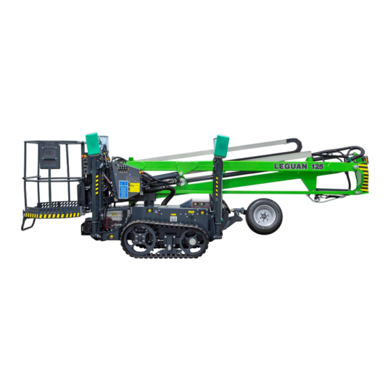
Using an access platform as a crane is prohibited. LEGUAN 125M2 has two rated loads and two work ranges. Loads of up to 135 kg permit working within the entire working range. For loads over 135 kg but below the maximum weight of 200 kg, the working range is restricted. - Page 8 Figure 1. LEGUAN 125M2 main parts...
-
Page 9: Technical Specifications
TECHNICAL SPECIFICATIONS Working height, cage load 12.5 m <135 kg 11.3 m 135–200 kg Platform height, cage load 10.5 m <135 kg 9.3 m 135–200 kg Outreach, cage load 6.5 m <135 kg 5.1 m 135–200 kg Safe working load 200 kg Transport length 5,158 mm... -
Page 10: Main Dimensions
Main dimensions Figure 2. LEGUAN 125M2 main dimensions (4WD wheels) Figure 3. LEGUAN 125M2 main dimensions (tracks) -
Page 11: Reach Diagram
Reach diagram Figure 4. Leguan 125M2 reach diagram Support pattern Figure 5. Leguan 125M2 support pattern... -
Page 12: Signs And Markings
9. Residual current device 10. Electric motor voltage 11. Max. outrigger force 12. Distance from energised electric wires and sound level on the platform 13. Binding points 14. Tyre pressure 15. ”Leguan 125” 3 12 Figure 6. Signs and markings... -
Page 13: Safety Instructions
SAFETY INSTRUCTIONS The operator must know and follow all safety instructions. The operator must receive sufficient instructions in order to be able to use the lift correctly and safely. This Operator’s Manual must always be kept in the machine. In order to prevent unauthorised use of the access platform, take the main switch key and the ignition key with you after concluding operation if the machine is left unsupervised. -
Page 14: Risk Of Tipping Over
In order to ensure the safe operation of this access platform, the manufacturer has conducted approved tests for the LEGUAN 125M2 in accordance with the standard EN 280:2015 static stability test in accordance with paragraph 6.1.4.2.1 and a dynamic overload test in accordance with paragraph 6.1.4.3. -
Page 15: Risk Of Collision
Risk of collision Adjust the drive speed so that it is safe with regard to the ground conditions. When operating the lift, take into account that visibility may be limited The operator must follow all regulations concerning the use of safety equipment on the work site Make sure that there are no overhead obstacles on the work site that could prohibit lifting of the platform, or objects that might cause a collision... -
Page 16: Risk Of Fire / Explosion
Risk of fire / explosion The machine must not be started in a place where one can smell LPG, petrol, solvent or other flammable substance Do not add fuel when the engine is running Charge the battery only in places with sufficient ventilation, where there is no open fire and no activity which could cause spark emissions (such as welding). -
Page 17: Controls And Switches
CONTROLS AND SWITCHES Control devices on the platform The platform’s controls and indicators on the control panel may be slightly different in different models. Indicators and switches that are marked as optional are not installed on all models. 1. 1st boom control lever 2. -
Page 18: The Base's Controls And Switches
The base’s controls and switches The base’s main power switch Using the main power switch disconnects the power circuit of the battery’s positive terminal. Except for the emergency lowering and GPS tracker (optional accessory), low-voltage functions are disabled when the power is switched off. DO NOT switch the power off if the booms are not in the transport position! The charger functions even when the power is off. -
Page 19: Emergency Lowering Button At Ground Level And Slewing Release
Emergency lowering button at ground level and slewing release 1. Emergency lowering, lower boom 2. Emergency lowering, upper boom 3. Slewing release lever 230 V connections and switches 1. 230V 50Hz, 16A connection cable, output either on the side or at the back (electric engine model) 2. -
Page 20: Lower Control Switches (Optional)
Lower control switches (optional) 1. Emergency stop 2. Ignition; stop - power on - start 3. Selection of the control position; upper control - lower control 4. Overload warning light 5. 1st boom control lever 6. 2nd boom control lever 7. -
Page 21: Starting The Machine
STARTING THE MACHINE Read this Operator’s Manual and the Operator’s Manual for the engine carefully before commencing operation. Read the safety instructions in this manual and make sure you understand them before commencing operation. It is the operator’s responsibility to understand and follow all operating and safety instructions. -
Page 22: Drive
DRIVE When transferring the platform, pay attention to the following factors: 1. Do not exceed maximum inclination for the drive. Make sure the driving surface is solid. 2. Secure tools and other materials to prevent them from falling or shifting. 3. -
Page 23: Determining The Gradient Of The Slope
Determining the gradient of the slope Measure the slope with a digital clinometer, or do as follows: Take a water level, a straight piece of wood (at least 1 m long), and a pocket tape measure. Place the wood on the gradient. Put the water level on the lower edge of the stick and lift the stick until it is in a horizontal position. -
Page 24: Fixing Nuts For The Tracks' Rear Sprocket
Fixing nuts for the tracks’ rear sprocket It is important to check the tightening of nuts on the rear sprocket (bigger track wheel) 2 days after commissioning the access platform. When driving with a new machine, the parts in the track system adapt to each other and “find their place”. - Page 25 Avoid repeated sharp turns. o By making wider and more gentle turns, you can avoid unnecessary wear of the tracks and/or tracks jumping off the sprockets. Avoid driving with one track on a level surface and one track on a gradient. o Always drive on an even surface.
-
Page 26: Operation Of The Outriggers
OPERATION OF THE OUTRIGGERS The outriggers are placed in the support position as follows: 1. Turn the ‘mode selection’ switch to the outrigger operation position. 2. Ensure that the four red outrigger pressure signal lights are on and that the green light does not light up! If the red outrigger pressure lights are not on, push all the outrigger levers up. -
Page 27: Use Of The Booms
In addition, the Leguan 125M2 machine is equipped with an overload protection system that prevents all boom motions if the load exceeds 200 kg or 135 kg when the extension is extended further than the permitted range. -
Page 28: Emergency Lowering And Emergency Use
EMERGENCY LOWERING AND EMERGENCY USE Electric lower controls If the operating power supply cuts off (fuel running out, power cut or damage to the extension cord), the booms can be lowered as follows: 1. Emergency lowering switches are located on the platform control panel and in the control system connection box. -
Page 29: Stopping Operation
STOPPING OPERATION After concluding operation: 1. Lower the booms down to transport position. 2. Lift the outriggers completely up to transport position. 3. Turn the ignition key to the ‘0’ position and take it with you. 4. Remove safety harnesses from the platform and take them with you (harnesses must be kept in their place and in their box/package). -
Page 30: Transport Of The Access Platform
TRANSPORT OF THE ACCESS PLATFORM The chassis and outriggers are equipped with lifting and binding points which are indicated with symbols. The machine may only be secured for transport from these binding points. The machine must always be lifted from the designated lifting points. When lifting, it is advisable to use a lifting beam in order to prevent the outriggers from getting damaged. - Page 31 There is an automatic hydraulic brake in the rear axle that engages automatically when the combustion engine/electric motor is not running. If the machine is transported on a trailer, a lorry or a similar vehicle, it must be secured carefully. There are four binding points marked on the corners of the chassis which make it easy to secure the machine.
-
Page 32: Instructions For Service, Maintenance And Inspections
Make sure that all labels are in place and readable. NOTE! All spare parts – especially electric components and sensors – must be original Leguan parts. Battery handling When handling the battery, bear in mind that: The battery contains corrosive sulfuric acid –... -
Page 33: Handling Of Fuel And Oil Products
If any signs of a leak are observed, place a piece of cardboard underneath the suspected component to determine the source. If you find a fault, operation of the access platform must be stopped immediately and the hose or the component must be replaced. Contact the Leguan service. -
Page 34: Maintenance And Inspections, Service Schedule
Maintenance and inspections, service schedule Regarding the service of the engine, also see the engine manufacturer’s Operator’s Manual. EM = engine manual CH = check CL = clean = replace A = adjust = first service after 50 h 200 h / 12 400 h / 24 Measure month... - Page 35 The wear pads on the telescopic boom must be checked and, when necessary, replaced at least every 5 years. The abovementioned service intervals are recommendations. If the operating conditions are challenging and/or the machine is in heavy duty use, the service and change intervals must be shortened.
-
Page 36: Service Instructions
SERVICE INSTRUCTIONS Greasing Greasing of the machine is of utmost importance to prevent wear in joints. Most of the joints are service free - however the slewing bearings must be greased in accordance with the maintenance schedule, using grease that contains EP (extreme pressure) additive. Outrigger bearings and articulation bearings in all hydraulic cylinders must be greased in accordance with the maintenance schedule. -
Page 37: Battery Check
Battery check Inspection of the battery (4) liquid level and terminals. In order to secure the activation process and safe operation, the battery must be inspected regularly. The battery liquid levels are checked by loosening the caps. Also inspect the battery terminals and clean them when necessary. NOTE! Clean the battery before loosening the caps to prevent dirt from entering the battery cells. -
Page 38: Hydraulic System Settings
Hydraulic system settings The hydraulic system has been adjusted to correct values at the factory and usually there is no need to adjust them. The figure shows the chassis valve housing opened. 1. Hydraulic pressure measurement fixture. All the machine hydraulic pressures are measured via this fixture. -
Page 39: Overload Protection Components
Overload protection components Overload control has been set to the correct values at the factory and it is strictly forbidden to change its settings. THERE IS A RISK OF THE ACCESS PLATFORM TIPPING OVER! The overload control mechanism is located between the working platform and the platform support and can be viewed by opening the protective cover located in the cage. -
Page 40: Electric Sensors
Electric sensors The transport position sensor S8 (1) is located between the combustion engine and the chassis. The plastic protection of the boom’s transport support must be adjusted in such a manner as to offer sufficient support without placing too much strain on the booms. -
Page 41: Inspection Of The Track Tightness And Adjustment
Inspection of the track tightness and adjustment The tightness of the track is inspected and adjusted with the access platform raised on the outriggers. The tracks must be inspected for the first time and adjusted, if necessary, after one hour of use. After this initial inspection, the tracks should be checked and adjusted once a week. At the same time, the sprocket bolts and nuts should be inspected to ensure that they have not loosened. -
Page 42: Repair Instructions
REPAIR INSTRUCTIONS Welding All load-carrying steel parts are manufactured from S420MC EN10149 sheet and S420MH/S355J2H EN10219 tubular pipe. Welding repairs may only be carried out by professional welders. When welding, use only methods and additives suited for the abovementioned steel qualities. SFS EN-ISO 5817 quality level D is suitable for all welding, except for load-bearing parts. -
Page 43: Instructions For Temporary Storage
INSTRUCTIONS FOR TEMPORARY STORAGE The cable of the + pole of the battery should be disconnected, if the access platform is being stored for a period longer than one month. The access platform must be protected and stored in an indoor storage facility or other covered space that cannot be accessed by unauthorised persons (a locked space) Make sure that chemical leaks during storage will not cause environmental harm, such as problems related to wastewater. -
Page 44: Troubleshooting
TROUBLESHOOTING The following table shows failures and malfunctions of the access platform and the ways to repair them. ISSUE CAUSE CORRECTIVE ACTION The motor does not start when When the work begins, the Place the booms on the transport the start lever is pulled booms do not rest on the supports using the emergency transport supports and the... - Page 45 ISSUE CAUSE CORRECTIVE ACTION The electric motor does not start Mains cable is not connected to Connect the plug to the when the start lever is pulled. network. 230V/16A output. The engine selection switch Turn the switch to the right located on the platform’s position.
- Page 46 ISSUE CAUSE CORRECTIVE ACTION The boom comes down on its Dirt in the load control valve or Clean valve with compressed own. a defective valve air, and if that does not help, change the valve. Clean valve with compressed Dirt in the emergency lowering air, and if that does not help, valve or a defective valve change the valve.
-
Page 47: Performed Service
PERFORMED SERVICE It is advisable to write down all service operations that are included in the periodical service. All services that have been performed during the warranty period must be noted on the list below, otherwise the manufacturer’s warranty will not be valid. The service operations mentioned in the maintenance schedule on page 24 must be recorded as follows: FIRST SERVICE, 1 MONTH SERVICE, 6 MONTH SERVICE, ETC.
Need help?
Do you have a question about the 125M2 and is the answer not in the manual?
Questions and answers