Table of Contents
Advertisement
Advertisement
Table of Contents

Related Manuals for Leguan 125


Summary of Contents for Leguan 125
- Page 1 Operators and Service Manual 2014- Version 6/2015 27.8.2015...
-
Page 2: Table Of Contents
TABLE OF CONTENTS page 1. INTRODUCTION AND WARRANTY CONDITIONS 1.1 I NTRODUCTION 1.2 W ARRANTY CONDITIONS 2. GENERAL INFORMATION 3. TECHNICAL SPECIFICATION, LEGUAN 125M1 3.1 R EACH DIAGRAM 4. SIGNS AND STICKERS 5. SAFETY INSTRUCTIONS ATTENTION ! 5.1 B EFORE STARTING OPERATION 5.2 O... - Page 3 _________________________________________________________________________________________ 18. TROUBLESHOOTING SERVICE HISTORY Attachments: Hydraulic schematic Electric schematic...
-
Page 4: Introduction And Warranty Conditions
1. INTRODUCTION AND WARRANTY CONDITIONS 1.1 Introduction LEGUAN LIFTS wants to thank you for purchasing this Leguan access platform. It is the result of Leguan’s long experience in design and manufacturing of access equipment. We ask you that you read and understand the contects of this manual completely before operating the access platform. - Page 5 _________________________________________________________________________________________ Warranty does not cover: damages caused by wrong or negligent use of this product, or mischief any repairs or modfications to the product, performed without the prior authorisation of the manufacturer damages caused by not following service and maintenance instructions adjustments, repairs and spare parts replacements caused by normal wear damages caused by excessive loads on the access platform, sudden unexpected incident, natural disaster...
- Page 6 TEKNISIÄ ERITELMIÄ: FOLLOWING TECHNICAL SPECIFICATIONS ARE USED WHEN THE MACHINERY WAS DESIGNED: Yhdenmukaistetut standardit: Harmonized Standards: EN280+A2 Ilmoitettu laitos/Notified Body INSPECTA TARKASTUS OY Testausraportti/Test Report 11573 Valmistaja / Manufacturer: Ylötie 10 LEGUAN LIFTS OY 33470 YLÖJÄRVI www.leguanlifts.com FINLAND e-mail : leguan@avanttecno.com...
-
Page 7: General Information
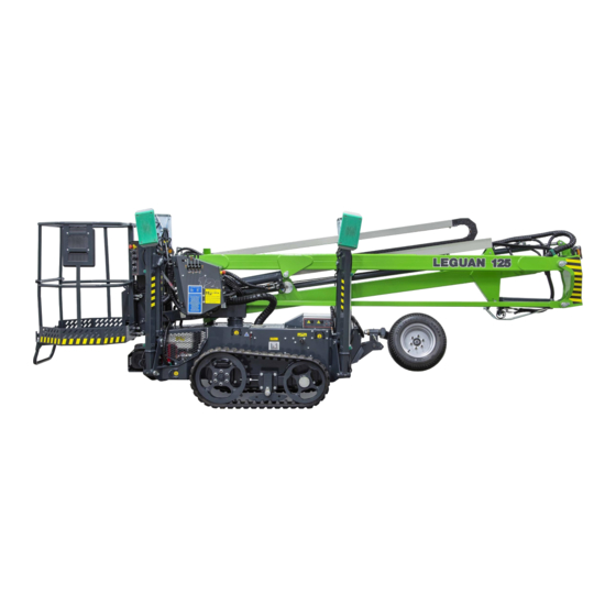
_________________________________________________________________________________________ 2. GENERAL INFORMATION LEGUAN 125M1 is a self propelled Mobile Elevating Work Platform – or commonly called access platform, designed for indoor and outdoor use. An access platform is destined for lifting of persons and their equipment only. It is not allowed to use an access platform as a crane. -
Page 8: Technical Specification, Leguan 125M1
_________________________________________________________________________________________ 3. TECHNICAL SPECIFICATION, LEGUAN 125M1 Working height, safe working load <135 kg 12,5 m safe working load 135 - 200 kg 11,3 m Max. platform height, SWL <135 kg 10,5 m SWL 135 – 200 kg 9,3 m Max. outreach, SWL <135 kg... - Page 9 _________________________________________________________________________________________...
-
Page 10: Reach Diagram
_________________________________________________________________________________________ 3.1 Reach diagram... -
Page 11: Signs And Stickers
7. Symbol stickers (pictograms) of controls 8. Emergency lowering 9. Residual current device 10. Voltage of electric motor 11. Max. support force 12. Distance from energized electric wires 13. Tie down points 14. Tyre pressure 15. LEGUAN 125 sticker 3 12... -
Page 12: Safety Instructions
_________________________________________________________________________________________ 5. SAFETY INSTRUCTIONS The operator must know and follow all safety instructions. The operator must receive sufficient instructions in ordert to be able to use the lift correctly and safely. This Operators Manual must always be kept in the box on the platform. ATTENTION ! In order to prevent unpermitted use of the access platform, take the main battery disconnect key that is located on ground level and the engine ignition key, if fitted, with you after ending... -
Page 13: Overturning Hazard
In order to ensure the safe operation of this access platform the manufacturer has conducted approved tests for the LEGUAN 125 in accordance with the standard EN280 +A2 : static stability test in accordance with paragraph 6.1.4.2.1 and dynamic overload tests in accordance with paragraph 6.1.4.3 of the EN280 +A2. -
Page 14: Electrocution Hazard
_________________________________________________________________________________________ 5.5 Electrocution hazard This access platform is not voltage insulated nor protected against contact with voltage carrying parts, or when approaching them. Do not touch the machine if it comes in contact with voltage carrying electric line. Persons on the platform or at ground level must not touch or operate the platform before power has been cut off from the electric line. -
Page 15: Controls
_________________________________________________________________________________________ 6. CONTROLS 6.1 Controls at platform The controls and indicators on the control panel at platform may be slightly different in different models. Indicators and switches that are marked as options are not mounted on all models.. 15 14 13 12 1. -
Page 16: Controls At Ground Level
_________________________________________________________________________________________ 6.2 Controls at ground level 6.2.1 Battery disconnect switch at ground level Battery disconnect switch connects and disconnects the circuit from the + line of the battery. When main current is switched off, all low voltage functions are cut off, except for emergency lowering. -
Page 17: 230V Connection And Switches
_________________________________________________________________________________________ 6.2.4 230V connection and switches 1. 230V 50Hz, 16A connecting cable: either on the side of chassis or in the rear next to electric motor. 2. Switch of residual current device. The switch must be in ”ON” position in order that any 230V device will work, including the 230V outlets. -
Page 18: Starting The Engine / Electric Motor
_________________________________________________________________________________________ 7. STARTING THE ENGINE / ELECTRIC MOTOR Read carefully this Operators Manual and also the Operators Manual for the engine before starting operation. Read and understand all safety instructions before starting operation. It is the operator’s responsibility to follow all operating and safety instructions. This access platform is destined for lifting of persons and additional load only. -
Page 19: Drive Control
– start the driving carefully and at low speed. Transmission of the LEGUAN 125 is hydrostatic. Each wheel is equipped with a hydraulic motor - the machine is four wheel drive. If the machine is equipped with rubber tracks there are two hydraulic motors in the track system. -
Page 20: Defining The Gradient Of The Slope
_________________________________________________________________________________________ 8.1 Defining the gradient of the slope Measure the slope with a digital clinometer, or do as follows: Take a water level, a straight piece of wood at least 1 m long, and a pocket tape measure. Put the wood stick on the gradient. Put the water level on the lower edge of the stick and lift the stick until it is in horizontal position. - Page 21 _________________________________________________________________________________________ 8.2.1 Instructions for working environment In order to increase the lifespan of the track system avoid driving on the following terrains or work sites: Environments with crushed stone, iron bars, scrap metal or similar recycling material. Rubber tracks are not designed for this kind of environments. ...
-
Page 22: Operation Of The Outriggers
LED indicators are still lit, press sharply on all four outrigger control levers. ATTENTION! If the green indicator of boom lifting is lit when the outriggers are not correctly deployed, the operation of this access platform is not allowed! Contact nearest Leguan service! -
Page 23: Operation Of The Booms
– or then it is lit all the time, operation must be stopped and function of the indicator and the system must me checked. 6. LEGUAN 125 is also equipped with an overload control system which prevents boom movements in case the 200 kg safe working load is exceeded, or in case the telescopic boom comes out more than allowed when load on the platform is over 135 kg. -
Page 24: Emergency Lowering
_________________________________________________________________________________________ 11. EMERGENCY LOWERING If the power supply for some reason cuts off (e.g. no fuel or electricity cuts off, or connecting cable fails) the booms can be lowered as follows 1. The lift is equipped with an electric emergency lowering system. There are emergency lowering buttons both on the platform and at ground level. -
Page 25: Transporting Instructions
_________________________________________________________________________________________ 13. TRANSPORTING INSTRUCTIONS Lower the booms down to transport position and lift the outriggers completely up to transport position. ATTENTION! Transporting of the access platform is allowed in transport position only. No persons or materials are allowed to be transported on the platform. The outriggers are equipped with lifting points from which the machine can be lifted if necessary. -
Page 26: Service, Maintenance And Inspection Instructions
Make sure that all stickers are in their place and readable. ATTENTION! All spare parts – especially electric components and sensors – must be original Leguan parts. Always remember when handling the battery: Battery contains corrosive sulfuric acid – handle the battery with care! When handling the battery wear protective clothing and eyewear. - Page 27 If you find a fault, operation of the access platform must be stopped immediately and the hose or the component must be replaced. Contact Leguan service.
- Page 28 _________________________________________________________________________________________ 14.2 Services and checks, maintenance schedule Regarding the service of the engine see also engine manufacturer’s Operators Manual = EM CH = Check CL= Clean R = Replace A = Adjust F = First service at 50 h Operation day month 100 h 200 h / 400 h /...
-
Page 29: Service Instructions
_________________________________________________________________________________________ 15. SERVICE INSTRUCTIONS 15.1 Greasing of the machine Greasing of the machine is of utmost importance in order to prevent wear in joints. Most of the joints are service free - however the pressure roller bearing of slewing on pedestal must be greased in accordance with the maintenance schedule, with grease containing EP (extreme pressure) additive. -
Page 30: Check Of Set Up Outrigger Control System
LEDs now light up and the green indicator doesn’t, the set up system works correctly. After this the setting of outriggers can be done as usual. ATTENTION! If the set up control system doesn’t work correctly, contact Leguan service. It is not allowed to use this access platform, and the failure/defect must be repaired before starting operation. - Page 31 _________________________________________________________________________________________ All cylinders – except for the self levelling ”slave” cylinder – are equipped with load holding valves (no. 1 in the picture left), which prevent cylinder movements in case e.g. a hydraulic hose fails. When using emergency lowering of the booms, the electric solenoid valve in the cylinder (no.
-
Page 32: Components In Overload Control System
<135 kg indicator goes out when there is clearly over 135 kg load on the platform, operation of the machine must be stopped immediately. Contact Leguan service. NEVER EXCEED SAFE WORKING LOAD! -
Page 33: Electric Sensors
_________________________________________________________________________________________ 15.10 Electric sensors Transport position sensor S8 is located inside the transport support at the front of the chassis. See picture left. Lower transport position sensor S4 is mounted on the adjustable transport support between the chassis and combustion engine, see picture below. -
Page 34: Check And Adjustment Of Track Tension
_________________________________________________________________________________________ 15.11 Check and adjustment of track tension Check and adjust track tension with the outriggers deployed and tracks lifted off the ground. First track tension check and eventual adjustment shall be made after first hour of operation. After that track tension shall be checked, and adjusted if needed, once a week. -
Page 35: Repair Instructions
_________________________________________________________________________________________ 16. REPAIR INSTRUCTIONS 16.1 Welding All load carrying steel parts are manufactured from S420MC EN10149 sheet and S420MH/S355J2H EN10219 tube. Welding repairs are only allowed to be carried out by professional welders. When welding, use only methods and additives suited for above mentioned steel qualities. SFS EN-ISO 5817 quality level D of imperfections in welding is suitable for all weldings, except for load carrying parts. - Page 36 _________________________________________________________________________________________ 18. TROUBLESHOOTING Following table shows eventual failures and malfunctions of the access platform and the ways how to repair them. PROBLEM REASON CORRECTIVE ACTION Engine/electric motor does not The booms are not properly Lower the booms down to start when ignition switch is down on the transport supports, transport supports by using moved to START position.
- Page 37 _________________________________________________________________________________________ PROBLEM REASON CORRECTIVE ACTION Electric motor does not start Mains 230V cable is not Connect 230V mains, min. 16A when ignition switch is moved to connected to network. wall socket fuse. Make sure that START position. the socket is electrified. Engine/electric motor selector Move switch to electric motor switch at platform is in engine...
- Page 38 _________________________________________________________________________________________ PROBLEM REASON CORRECTIVE ACTION Boom(s) come down by itself. Dirt in load control valve or Clean valve with compressed air, if that doesn’t help change faulty valve. valve. Dirt in emergency lowering Clean valve with compressed air, if that doesn’t help change valve or faulty valve.
- Page 39 _________________________________________________________________________________________ 18. SERVICE HISTORY It is advisable to write down all service operations that are included in the periodical service. All services that have been made during the warranty period must be noted on the list below, otherwise the manufacturer’s warranty will expire. The service operations mentioned in the maintenance schedule on page 28 shall be noted as follows: FIRST SERVICE, 1 MONTH SERVICE, 6 MONTHS SERVICE etc.
Need help?
Do you have a question about the 125 and is the answer not in the manual?
Questions and answers