
Related Manuals for Sieg X2.7


Summary of Contents for Sieg X2.7
-
Page 1: Instruction Manual
BENCH MILL MACHINE Instruction manual Please read this manual thoroughly and follow all directions carefully... - Page 2 IMPORTANT SAFETY INSTRUCTION READ ALL INSTRUCTIONS AND WARNINGS BEFORE USING THIS TOOL Operator COMMON SENSE AND CAUTION ARE FACTORS WHICH CANNOT BE BUILT INTO ANY PRODUCT. THESE FACTORS MUST BE SUPPLIED BY THE OPERATOR. PLEASE REMEMBER: 1. When using electric tools, machines or equipment, basic safety precautions should always be followed to reduce the risk of fire, electric shock, and personal injury.
- Page 3 IF THERE IS ANY QUESTION ABOUT A CONDITION BEING SAFE OR UNSAFE, DO NOT OPERATE THE TOOL! Grounding Instructions This machine has a three-prong plug, the third prong is the ground. Plug this cord only into a three-prong receptacle. Do not attempt to defeat the protection the ground wire provides by cutting off the round prong.
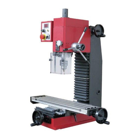
- Page 4 FEATURE Base Cross feed handwheel Long worktable Fuselage (with protect cover) Drill chuck with arbor Protective dust guard assembly Spindle sleeve locking handle Depth display Emergency stop switch Knob with potentiometer Electric control box Speed display Light Forward/0/Reverse switch Fine feeding handle Spindle box Vertical feed handwheel Fuselage back cover...
- Page 5 Installation CAUTION! DO NOT ATTEMPT TO USE THE MACHINE UNTIL INSTALLTION IS CAMPLETED, AND ALL PRELIMINARY CHECKS HAVE BEEN MADE IN ACCORDANCE WITH THIS MANUAL. MOUNTING THE MACHINE The machine should be mounted on a strong, heavy workbench, of sufficient height so that you do not need to bend your back to perform normal operations.
- Page 6 Operation 1. Before starts to use this machine, operator should go through the instructions carefully so as to acquaint with the construction of the machines, the functions of the various controls and also the driving systems. 2. This machine uses touching button (see operation panel below), operating steps refer to the flow chart.
- Page 7 position, the spindle will stop. 4. When you control the mill and need quickly stop the spindle speed, you can clap the emergency stop switch (A), as this time the fault yellow light ( E) will bright. If you need restart the mill you need turn the F/O/R switch (D) to “0” position, then control as 1-2-3 steps.
- Page 8 Parts drawing ( 1 / MT3 ) --the spindle taper is MT3...
- Page 9 Parts list ( 1 / MT3 ) --the spindle taper is MT3 Part No. Drawing No. Description Q'ty .1-1 XN3A0201 Spindle box .1-2 GB 818-85 - M4 x 6 Cross recessed small pan head screw H M3*8 .1-3 X3C0219 Spindle below oil seal ring I .1-4 X20206 B16 taper shank...
- Page 10 Part No. Drawing No. Description Q'ty .1-46 XN3A0206 Motor connect plate .1-47 GB273.2-87-单排 7/70 Thrust ball bearing single 7/70 .1-48 XN3A0209 Worm shaft .1-49 XN3A0203 Worm eccentric sleeve .1-50 X3C021100 Tighten the top rod .1-51 GB 119-86 - A 3 x 10 Round pin A3*10 .1-52 GB 301-84 - 8106...
- Page 11 Parts drawing ( 2 / R8 ) --the spindle taper is R8...
- Page 12 Parts list ( 2 / R8 ) --the spindle taper is R8. Part No. Drawing No. Description Q'ty .2-1 XN3A0201 Spindle box .2-2 X3C02A02 R8 spindle sleeve .2-3 X3C02A01 R8 spindle .2-4 XN3A0215 Base plate .2-5 XN3A0204 Gear shaft .2-6 XN3A0210 Bevel gear .2-7...
- Page 13 Part No. Drawing No. Description Q'ty .2-48 GB273.2-87-7/70 Thrust ball bearing single 7/70 .2-49 XN3A0203 Worm eccentric sleeve .2-50 XN3A0209 Worm shaft .2-51 Timing belt HTD-M5 385(77T) .2-52 GB 119-86 - A 3 x 10 Round pin A3*10 .2-53 GB 819-85 - M5x25 Cross recessed counter head screws M5*25 .2-54 GB 97.1-85 - 6...
- Page 14 Parts drawing ( 3 )
- Page 15 Parts list (3) --- note: The no. With “*” means the part showing in metric. Part No. Drawing No. Description Q'ty .3-1 XN3A0901 Column .3-2* XN3A0903A Metric rise and down leadscrew .3-3* XN3A0908A Metric rise and down locking nut .3-4* XN3A0907A Metric rise and down leadscrew nut .3-5...
- Page 16 Parts drawing ( 4 )
- Page 17 Parts list (4) --- note: The no. With “*” means the part showing in metric. Part No. Drawing No. Description Q'ty .4-1 X31136 The left bracket cover .4-2 XN3A1106 Left cover .4-3 X31131 Longitudinal leadscrew rod bracket left sleeve .4-4 XN3A1102 Work table .4-5*...
- Page 18 Parts drawing ( 5 )
- Page 19 Parts list ( 5 ) (Note: some type without the protective guard assembled) Part No. Drawing No. Description Q'ty .5-1 XN3A2305 Splash guard I .5-2 XN3A2304 Splash guard II .5-3 X20002 Filler strip .5-4 GB 818-85 - M4*6 Cross recessed counter head screws M5*6 .5-5 X20003 Dust guard...
- Page 20 Parts drawing ( 6 )
- Page 21 Parts list ( 6 ) Part No. Drawing No. Description Q'ty .6-1 GB 846-85 - ST2.9 x 9.5 Tapping screw .6-2 ZH-A Change-over switch .6-3 HY57B Emergency stop .6-4 Lampholder .6-5 RSD-27 Digital readout .6-6 WH24-1 4.7K Potentionmeter φ23 .6-7 Knob .6-8 XN3A1802...
-
Page 22: Packing List
Packing List Name Description Q'ty Remarks Bench Mill type: X2.7 or SX2.7 1 set Fuse 110V/20A or 230V/10A 1 pce. Manual manual 1 pce. S1*S2: 8*10、14*17、17*19 Double end wrench each 1 S: 3、4、5、6、8 L hex wrench each 1 U wrench assembly X3C004 1 pce. - Page 23 Circuit drawing (for 230V machine only)
- Page 24 Circuit drawing (for 110V machine only)
Need help?
Do you have a question about the X2.7 and is the answer not in the manual?
Questions and answers