
Related Manuals for Sieg SX1P


Summary of Contents for Sieg SX1P
-
Page 1: Instruction Manual
MICRO MILL Instruction Manual SX1P Read all instructions and warning before using this tool... -
Page 2: Table Of Contents
CONTENTS CHAPTER 1 SPECIFICATION 1-1 Machine specification CHAPTER 2 MACHINE INSTALLATION 2-1 Fundamental locating of the machine 2-2 Preparation before operation CHAPTER 3 PREVENTION AND MAINTENANCE 3-1 Prevention and maintenance 3-2 Maintenance of cutter and taper shank 3-3 Mechanics lubrication CHAPTER 4 MACHINE STRUCTURE 4-1 External feature 4-2 Assembly parts... - Page 3 Some Safety Features of this Machine a) Purpose of this machine: This machine is designed for drilling, deep milling and face milling of small work piece with limit . If the operator intend to use this machine beyond our design purpose, please contract the manufacturer or your dealer before operation .
-
Page 4: Chapter 1 Specification
CHAPTER 1 SPECIFICATION This is a MICRO milling machine with multiple functions on either face mill or drill. There are various sizes and kinds of cutter currently. It’s very easy to purchase , that can apply different function to insure you work more accurate and more efficient as long as you change the cutter upon your demand. -
Page 5: Chapter 2 Machine Installation
CHAPTER 2 MACHINE INSTALLATION 2-1 Fundamental Locating of The Machine The machine should be fixed on the working table with four Hexagon bolts. Please install it to an appropriate location in order to demand the precision requirements of the machine. The Selection of The Installing Location (1) The working table should have a flat surface. -
Page 6: Chapter 3 Prevention And Maintenance
8. Turn on the machine and check the direction of spindle rotating (clockwise). 9. Operate Longitudinal Axis (Working table), Cross Axis (Saddle seat), ’ Vertical Axis (Fuselage) to ensure it s in normal condition, 10. During the operation , watch out while you’re manipulating the machine. If there is any unusual situation, stop operating and repair immediately. - Page 7 (1) Please watch out the operation while you’re manipulating the machine. In case that there is any unusual phenomena, please stop and repair immediately. (3) Check whether the spindle is over-swing. (4) Check whether each bolt and nut is loosen. (5) Examine the overall circuit (contact points conductor, plugs and switches) to ensure its normal condition.
-
Page 8: Mechanics Lubrication
more convenient. (3)Draw bar and chuck have their own wrenches. For your convenience, please keep the wrenches near by the machine and never operate the machine with inappropriate tools. (4)Please use wrench to tight the nuts and never use other tools such as steel hammer to do so. -
Page 9: Chapter 4 Machine Structure
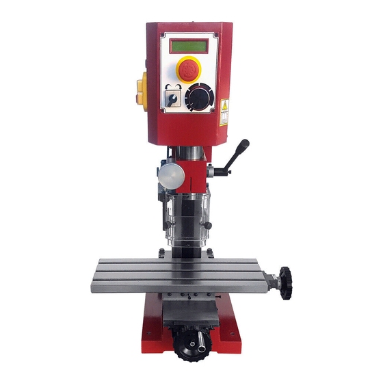
CHAPTER 4 MACHINE STRUCTURE 4-1 External Feature 1.Lifting Handwheel 11.Base 2.Revolving speed display screen 12.Cross Feed Handwheel 3.Scram button 13. Main spindle box 4.Forward/off/Reverse Switch 14.Dial(With depth setting function) 5.Variable Speed Control Knob* 15.Control lever 6.Adjustment hand 16.Column Fuse box 17.Clutch knob 8.Work table 18.Lock handle... - Page 10 4-2 Parts Diagram...
- Page 11 Part list Part NO. ERP NO. Description LX109A01 Column rail GB 5780-86 - M8x35 Screw M8x35 GB 93-87 - M8 Spring washer M8 LX10254 Washer GB118-86 6x26 Pin 6X26 LX11103A LX11106 Screw nut GB 70-85 - M6 x 25 Screw M6*25 LX11111 Cross wedge LX11104...
- Page 12 Part NO. ERP NO. Description YE013001 Cable joint YE00503018 Scram button HY57B YE00504005 Change-over switch ZH-A YE008007 Potentionmeter knob DSX12511 Electricity label YE00208002 X-1 small plate GB 818-85 - M4 x 8 Small phillips head screw GB 845-85 - ST2.9 x 6.5 - C - H Tapping screw GB 818-85 - M5 x 8 Small phillips head screw...
- Page 13 Part NO. ERP NO. Description LX10210 Wedge LX1025300 Handle GB 75-85 - M5 x 20 Headless set screw GB 41-86 - M 5 Nut M4 GB 70-85 - M5 x 12 Screw M5 x 12 LX10254 Washer GB 818-85 - M3 x 5 Small phillips head screw GB 818-85 - M4 x 6 Small phillips head screw...
- Page 14 Part NO. ERP NO. Description LSX1P0203 Fasten screw LSX1P0207 Protective sleeve LX10222 B12 Taper shank shaft LSX1P1101 Footing...
-
Page 15: Chapter 5 Mechanism Adjustment
CHAPTER 5 MECHANISM ADJUSTMENT 5.1 Installation and Removal of Taper shank □Electrical operation (1) Check the power, put power plug into the socket, open the jerk stop switch, anticlockwise turn the speed control potentiometer to “0” position, press the electromagnetic green start switch, then the power on liquid crystal display bright, clockwise adjust the potentiometer knob, and then the... -
Page 16: Travel Adjustment
rotation multi-purpose operating handle to making the milling processing.. (6)Please lock spindle box and spindle when milling parts, at the same please lock the longitudinal and transverse plug iron according your need. (7) Please loosen the screw (a) , transfer the spindle safety cover(b), use a wrench(c) to loosen the draw bar, and then use hammer to use hammer loosing the taper shank(f) and spindle hole. -
Page 17: Chapter 6 Operation And Notice For Use
In order to ensure the precision, the pressure between the two elements needs to be adjusted appropriately because of abrasion which the machine produced from the contact motion for same time( about one year). The following items need to make adjustment 1. -
Page 18: Operation Attention
1. According to Chp5, replacement of chuck and tool. Install appropriate adjustment and tighten it certainly. 2.Select appropriate speed level. ( ATTENTION: When spindle is running, don’t change the HIGH/LOW speed ! ) 3. Use press cake or fixture set the workpiece on the working table. 4.Adjust working table (Longitudinal Axis (Y)) and Saddle seat (Cross Axis (X)) in position. -
Page 19: Chapter 7 General Safety Instruction
3. Please inform our dealer to assign professional person to deal with the action beyond extent of individual maintenance and protection. CHAPTER 7 GENERAL SAFETY INSTRUCTION Warning! When using electric tools, basic safety precautions should always be followed to reduce the risk of fire, electric shock and personal injury, including the following. - Page 20 -Use clamp or a voice to hold the work. It is start than using your hand and it frees both hands to operate the tool. 13. Do not overreach. - Keep proper footing and balance at all times. 14. Maintain tools with care. Keep cutting tool sharp and clean for better and safer performance.
-
Page 21: Chapter 8 Electricity
CHAPTER 8 Electricity Electrical Circuit Diagram 220~240V/50-60Hz (see the label) - Page 22 Electrical Circuit Diagram 100~120V/50-60Hz ( see the label)
-
Page 23: Chapter 9 Packing List
CHAPTER 9 Packing List Description Manual Wrench 3、4、6 Each1 Double end wrench 5.5*7;8*10 Each1 Hook spanner 38-42 Oil cup Fuse 110V/4A or 230V/2A Drill chuck and key T-nut Handle lever bolt Handle casing Lag screw spanner □8 Gear change lever...
Need help?
Do you have a question about the SX1P and is the answer not in the manual?
Questions and answers