Table of Contents

Subscribe to Our Youtube Channel
Related Manuals for Brivis ICE DONSC13Z7


Summary of Contents for Brivis ICE DONSC13Z7
- Page 1 Brivis ICE Inverter R410A INSTALLATION, START-UP, MAINTENANCE INSTRUCTIONS & USER OPERATING GUIDE PLEASE READ THESE INSTRUCTIONS CAREFULLY BEFORE INSTALLING & USING THIS PRODUCT Bonus offer when you register your product online brivis.com.au...
-
Page 2: Table Of Contents
4.2 Condensate Drain / Safety Tray ......................9 4.3 Minimum Service Access.........................9 4.4 Electrical Connection ..........................9 4.5 System and Ductwork Design .......................11 4.6 Brivis Heater Thermistor position (if applicable) ..................11 4.7 Filtration ..............................11 4.8 General Arrangement Drawings ......................12 5.0 OUTDOOR UNIT INSTALLATION ......................13 5.1 Location ..............................13... - Page 3 2.1 Brivis Customer Care Program......................33 2.2 Brivis Customer Care Program Membership..................34 2.3 ICE Warranty Card Form – or Register on line at brivis.com.au ............34 2.4 Terms of Warranty – Australia and New Zealand .................35 Specifications subject to change without notice. © 2013 Brivis Climate Systems Pty. Ltd.
-
Page 4: Installation, Start-Up & Maintenance Instructions
1.1 Brivis ICE R410a Inverter Range The Brivis Inverter ICE series is a refrigerated cooling split only type air conditioner designed for connection to compatible Brivis Ducted Gas Heaters. Brivis Inverter ICE utilises the heating system’s ductwork and air circulation fan to distribute cool, filtered refrigerated air. -
Page 5: Codes / Regulations
1.3 Codes / Regulations Brivis ICE units must be installed, serviced or repaired in accordance with these instructions and related regulations, codes, standards, and authorities. These include but may not be limited to: Ozone Protection and Synthetic Greenhouse Gas Management Regulations 1995 •... -
Page 6: Starting Collars
2.2 Starting Collars Insert starting collar (pop) into the hole in pop plate, ensuring pop flange is placed over the inner supply air wall of the cabinet. Spread the pop flange to fit tight in the cabinet’s hole with the notch side of the collar over lapping the other. Secure the pops with the rivets supplied. -
Page 7: Outdoor Unit
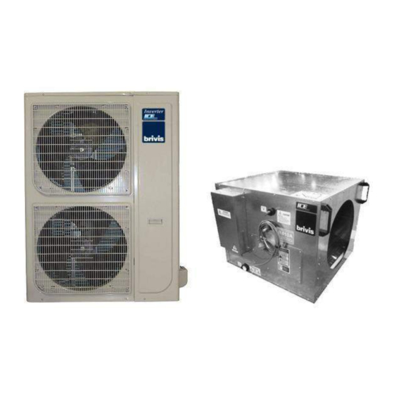
2.4 Outdoor Unit Fig. 5 - Outdoor Units DONSC10Z7 DONSC13Z7 & 15Z7... -
Page 8: Typical Installation
• unit. One end of the cable has to be earthed. If the Brivis Heater requires a remote thermistor installed in the supply air ductwork, position it in the supply air • starting collar (discharge pop) of the cooling coil (see Section 4.6) -
Page 9: Location
Safety Tray must also be separately drained, arranged to terminate in a position where the home owner can see if • water is dripping from the outlet. Please instruct the end user to call their Installer or Brivis Service should they notice water dripping from the Safety Tray drain outlet 4.3 Minimum Service Access... - Page 10 The unit is pre-wired with a 3-pin plug and lead, and should be plugged into a standard 10 Amp 220 to 240 Volt fixed switched socket outlet adjacent to the unit, in a convenient location so it can be turned OFF quickly and easily. Note: A qualified electrician must install the 220 to 240 Volt wiring according to local regulations.
-
Page 11: System And Ductwork Design
4.5 System and Ductwork Design Good duct design and sizing are essential to every Brivis ICE cooling system. Use the Brivis “SuperSizeGuide”, Technical Data Sheets or HB276. In general: Ductwork should be airtight and have a minimum insulation rating of R1.0 •... -
Page 12: General Arrangement Drawings
4.8 General Arrangement Drawings Fig. 9 - Indoor Unit Dimensions – Model DINXU15Z7 Fig. 10 - Indoor Unit Dimensions Models - DINXU10Z7 & DINXU13Z7... -
Page 13: Outdoor Unit Installation
1.5mm • Note: There is time delay built into the Outdoor Condensing Unit to prevent compressor short cycling on rapid calls from the thermostat for cooling. Time delays providing this protection are built into the recommended Brivis Controllers. -
Page 14: Wiring Diagrams
5.4 Wiring Diagrams Fig. 11 – Typical Indoor Unit Wiring Diagram (DINXU SERIES) shielded Or to the **Shielded cable** Classic thermostat - Refer to Fig 13... - Page 15 StarPro unit please refer to the associated heater installer’s manual. Your zoning requirements may require a 'Brivis Network 516 module' (Part No. B023178), please refer to the associated heater installer’s manual Note: For ICE connection to a Brivis SP4, SP5 or SP6 StarPro heater, a...
- Page 16 Fig. 13 – Wiring Circuit for Brivis Classic Series Heaters with ICE Using Brivis Programmable Thermostat HCCA621 Electronic Control Module Fuse 2A EARTH Fan Speed Red LED G W R 12AC INDOOR UNIT ELECTRIC BOX Electronic Thermostat Contact Brivis Technical Support for information on superseded Brivis Heaters.
-
Page 17: General Arrangement Drawings & Clearance Requirements
5.5 General Arrangement Drawings & Clearance Requirements Fig. 15.a – Outdoor Unit: DONSC10Z7 Fig. 15.b – Outdoor Unit: DONSC15Z7 & DONSC13Z7 Unit mm MODEL DONSC15Z7 633.5 1369 DONSC13Z7 633.5 1369 DONSC10Z7 Table 2 – Brivis Inverter Outdoor Unit Dimensions... -
Page 18: Refrigeration Charge & Pipe-Work
Fig. 16 – Outdoor Unit Clearances 6.0 REFRIGERATION CHARGE & PIPE-WORK WARNING: Both indoor and outdoor units come delivered under positive pressure • The Outdoor Unit is charged with sufficient R410a refrigerant for an interconnecting pipe run of 10m actual length •... -
Page 19: Piping Design
6.1 Piping Design Pipe-work shall be installed in a manner which prevents drainage of liquid into the compressor and ensures • adequate oil return During operation, temperature of gas pipe and liquid pipe shall be over-heating or over-cooling extremely. • Therefore, it is necessary to carry out insulation;... -
Page 20: Pipe-Work Connection
6.2 Pipe-work connection Sweat connection: Locate the suction & liquid pipe service valves in the compressor compartment by removing the service access • panel Check that the service valves are tightly closed (Service Ball valves have been provided for suction and liquid •... -
Page 21: Expelling The Air With The Vacuum Pump
Be sure to use both a spanner and torque wrench together when connecting/disconnecting pipe to/from the unit. • NOTE: Too large torque will harm the bell-mouthing and too small will cause leakage. Please determine the torque according to the following table. Leak test the unit after finishing the connection. Table 4 –... -
Page 22: Charging The System
Fig. 18 – Vacuum Pump Application 6.4 Charging the system Once all electrical connections are correctly made, the unit is ready to be commissioned. Refrigerant may only be added after performing a leak test and system evacuation. Start the system in cool mode and allow it to stabilise before checking liquid line sub-cooling and compressor suction superheat. -
Page 23: Start-Up And Commissioning
2537 2664 1045 2796 1113 2932 1183 3073 1257 3219 1334 3371 1414 3527 1497 3689 1584 3857 1674 4031 1768 4210 Table 5– Saturated Pressure-Temperature R410a FAILURE TO COMPLETE PROPER START UP AND COMMISSIONING MAY VOID BRIVIS PRODUCT WARRANTY... -
Page 24: Sequence Of Operation
7.1 Sequence of Operation Check correct sequence of operation, then proceed to instruct customer on correct thermostat operation for refrigerated cooling. Refer to the thermostat operating instructions. . Ventilation Set the thermostat to the fan only mode. The fan only will start and operate continuously. Cooling On a call for cooling the compressor and outdoor fan/s will start and cycle in response to the thermostat to maintain the desired room temperature. -
Page 25: Cooling Capacity Tables
7.2 Cooling Capacity Tables Return Air Temperature Air Temperature Entering Dry Bulb ° C Wet Bulb ° C Dry Bulb ° C Wet Bulb ° C Dry Bulb ° C Wet Bulb ° C Outdoor Unit ° C 15.170 15.902 16.196 TC kW 11.618... -
Page 26: Specifications
19 ~ 32 19 ~ 32 © Brivis Climate Systems. All specifications are subject to change without notification. Contact Brivis marketing department with any queries. Equipment rated in accordance with AS 3823.3 - 2009 Table 9 – Brivis ICE INVERTER - Technical Specifications... -
Page 27: Commissioning Sheet
7.4 Commissioning Sheet Installer; please complete all sections of this form. SYSTEM INFORMATION ICE MODEL SERIAL No. (Outdoor Unit) (Outdoor Unit) ICE MODEL SERIAL No. (Indoor Unit) (Indoor Unit) HEATER MODEL HEATER SERIAL No. INSTALLED BY/ DATE PRE START-UP (Please tick boxes below as each item is completed). VERIFY THAT ALL PACKAGING MATERIALS HAVE BEEN REMOVED FROM UNIT. -
Page 28: User Operating Guide
• 1.1 Privacy Notification Brivis Climate Systems Pty Ltd is the registered owner of the Brivis brand. Brivis will collect "personal information’’ from you when you complete your warranty and maintenance registration form. This personal information is collected under the guidance of the Privacy Information Protection Act 1998. -
Page 29: Appliance Operating Symbols
On/Off Function Mode Variable programs Rotary Dial The Display Screen: Provides you with information about the system. The Screen shows the current time via a • Digital Clock in the top left corner, the Day of the Week on the left-hand side, and the operating mode selected at the bottom. -
Page 30: Operating The Fan Only
This code contains information that will enable Brivis to deal quickly and easily with anything that requires their attention. With many of them you will be asked to contact Brivis Service and pass on the message, the model and type of appliance. -
Page 31: Locking/Unlocking The Networker
1.7 Locking/Unlocking the Networker To prevent any unwanted alterations being made to the operational settings, the Networker can be locked via a 4-digit PIN number. In the case of dual Networkers, if one is locked the other is also locked. There can be up to 3 PIN numbers stored into the controller, which allows the Networker to be locked or unlocked by various users. - Page 32 Resetting PIN Numbers If you have forgotten or misplaced your user PIN numbers, you can reset all the PIN numbers to the default setting of “1111”. The user PIN numbers can only be reset from the Master Networker; the Slave Networker (where applic.) can only lock and unlock the Networkers and cannot access the PIN numbers.
-
Page 33: Service, Maintenance And Warranty
Brivis products are renowned for providing years of trouble free performance. To be at their most efficient performance, like most things, they need a little care. So to ensure that every Brivis unit is always in perfect condition we have established the Brivis Care Program for our valued customers. -
Page 34: Brivis Customer Care Program Membership
2.2 Brivis Customer Care Program Membership The Brivis Customer Care Program is designed to help you get the most out of your new unit. We will contact you before each winter or summer season with some terrific discounted offers for preventative maintenance services which will keep your Brivis unit in great condition! If you would like to join our Brivis Care Program please complete the following information with the warranty form. -
Page 35: Terms Of Warranty - Australia And New Zealand
2.4 Terms of Warranty – Australia and New Zealand Brivis Climate Systems Pty. Ltd. ABN 64 096 079 088, AU24752 61 Malcolm Rd, Braeside, VIC 3195. Definitions The terms listed below shall have the following meanings: means an independent service contractor authorised by Brivis or Brivis “Authorised Service Representative”... - Page 36 Brivis within 30 days of a defect developing, that a claim is being made under this Warranty; and provides, in support of the claim made under this Warranty, a Proof of Purchase. 3.6 This document represents the only Warranty given by Brivis and no other person or organisation is authorised by Brivis to offer any alternative.
- Page 37 Travel, Transport & Access Costs 6.1 The Purchaser must pay freight charges, in-transit insurance expenses and travelling costs for repairs/replacements under this Warranty, that are required to be performed 100km or more from the nearest Brivis branch or Authorised Service Representative.
- Page 38 For Australian Warranty Claims call 1300 Brivis (1300 274847) or send to Brivis Warranty Claims 61 Malcolm Road, Braeside VIC 3195. For New Zealand Warranty Service call 0800 WARMAIR (0800 9276 247) - Brivis only. The PURCHASER WILL BE CHARGED for work done or a service call(s) if:- the problem is not covered by these Terms of Warranty;...
- Page 39 Notes:...
- Page 40 © Brivis Climate Systems Pty. Ltd. 2013 All rights reserved. No part of these documents may be used in any way or form without prior written consent from Brivis Climate Systems Pty Ltd. Part Number: B061012 Aug 2013 Brivis Climate System Pty Ltd...
Need help?
Do you have a question about the ICE DONSC13Z7 and is the answer not in the manual?
Questions and answers