Table of Contents
Advertisement
Quick Links
ELMDENE INTERNATIONAL LIMITED
3 KEEL CLOSE
INTERCHANGE PARK
PORTSMOUTH
HAMPSHIRE
PO3 5QD, UK
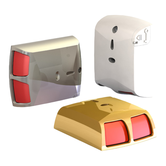
ELM-PA-G3-X Panic Button Guide
X is colour code:
ELM-PA-G3-W White, ELM-PA-G3-B Brass, ELM-PA-G3-SS Steel
ELM-PA-G3-BK Black
Panic alarm trigger device with two push buttons
Meets the requirements of
PD6662: 20
50131-1:2006.
A range of aesthetically pleasing two button panic alarm (PA) devices available with black,
white, brass or stainless steel appearance covers. Suitable for commercial and domestic
.
installation
Features include:
• Silent two button operation
• Compliant with PD6662: 2010, and the requirements of EN 50131-1:2006, Security
grade 3, Environmental class II.
• Suitable for use under the ACPO "10 point plan" for false PA reduction
• Integral, selectable resistor values for easy FSL connection to most alarm control
panels.
• Alternative double pole wiring option
• Spare terminals for connection of multiple units
• Key operated mechanical reset
• Selectable normally open or normally closed alarm contacts
• Cover and removal from wall tamper (normally closed)
• Visual indication of ready or latched state
Specifications
Temperature Range
-10
°C to+40°C
Dimensions
62 x 80 x 27mm
Contact
Power Handling
10VA
Voltage Rating
30Vdc
Current Rating
1.0A Max
Resistance
<300mohms
8
Operating Life
>1 x 10 operations
2015 Elmdene International Ltd
PAK200464 Feb 2015 Iss 03C
Technical Support Line + 44 (0) 2392 696638
TEL: +44 (0) 23 9269 6638
FAX: +44 (0) 23 9266 0483
www.elmdene.co.uk
10 at Grade 3, Environmental Class II
and EN
Setting reed - Normally Open (N.O.) or Normally Closed (N.C.)
Default is set to Normally closed. Please skip this section if this is the required setting.
1.
Tab
Tab
Follow steps 1&2 in reverse order to re-assemble. Take care not to damage the reed switch.
Wall Mounting
Top mounting
screw hole
Bottom mounting
screw hole
1. Press both buttons to move mechanism out of the way and gain access to the bottom fixing hole.
2. Mark positions of holes on the wall.
3. Drill holes to required depth and use appropriate wall plugs or fixings (No. 6 / 5mm).
4. Drive bottom
countersunk
5. Insert top
pan head
the PCB tamper breakout.
6.
Use friction adjustment screw to ensure sliding mechanism does not move without being pushed
by buttons or reset key. DO NOT OVERTIGHTEN
7. Angle lid as shown above. Slide upward
Use of the PA button
1. Push both buttons together to operate. After use
indicator will be red (latched).
2. To reset insert the key into the slot as shown.
3. Turn key clockwise as far as it will turn (about 120
degrees) to reset the PA.
4. Turn the key anticlockwise back to the start and remove it.
5. Indicator will now be yellow (ready).
Correct Use of PA Buttons
PA buttons should be installed in accordance with any applicable
regulations relating to panic alarms. Potential users should be advised in
the use of the PA.
Page 1
Normally Closed
3.
2.
(Factory Default)
Normally
Open
Friction
Adjustment
Screw
screw through base and into wall.
screw through PCB and plastic and screw into wall.
before
pushing lid closed. Fasten lid shut with screw.
1. Remove PCB by gently
bending the two tabs back
and pull the board up and
out.
2. Remove the sliding
mechanism (you may need
to loosen the friction
adjustment screw).
3. Push out magnet from other
side and swap to desired
position.
Take care not to snap
Page 2
Advertisement
Table of Contents

Subscribe to Our Youtube Channel
Related Manuals for Elmdene ELM-PA-G3 series


Summary of Contents for Elmdene ELM-PA-G3 series
- Page 1 Potential users should be advised in Operating Life >1 x 10 operations the use of the PA. 2015 Elmdene International Ltd PAK200464 Feb 2015 Iss 03C Page 1 Page 2 Technical Support Line + 44 (0) 2392 696638...
- Page 2 FSL Wiring Wiring the PA Button Two PA (Series Resistor Configuration) Single PA (Parallel or Series) Connections to the PA button are made via the screw terminals numbered 1 to 6. Configuration of the resistor values to match the alarm panel is by link jumpers. See the table below to find the resistor values and series or parallel option Control needed.
Need help?
Do you have a question about the ELM-PA-G3 series and is the answer not in the manual?
Questions and answers