Generac Power Systems 15 kW EcoGen Owner's Manual
60hz air-cooled generator
Hide thumbs
Also See for 15 kW EcoGen:
- User manual ,
- Installation manuallines (60 pages) ,
- Owner's manual (48 pages)
Table of Contents
Advertisement
Quick Links
Para español, visita:
http://www.generac.com/service-support/product-support-lookup
Pour le français, visiter :
http://www.generac.com/service-support/product-support-lookup
SAVE THIS MANUAL FOR FUTURE REFERENCE
Owner's Manual
60 Hz Air-Cooled Generators
15 kW EcoGen™
This product is not intended to be used in
a critical life support application. Failure to
adhere to this warning could result in
death or serious injury.
Register your Generac product at:
WWW.GENERAC.COM
1-888-GENERAC
(888-436-3722)
000918
WARNING
(000209a)
Advertisement
Table of Contents
Troubleshooting

Subscribe to Our Youtube Channel
Related Manuals for Generac Power Systems 15 kW EcoGen


Summary of Contents for Generac Power Systems 15 kW EcoGen
- Page 1 Owner’s Manual 60 Hz Air-Cooled Generators 15 kW EcoGen™ 000918 WARNING This product is not intended to be used in a critical life support application. Failure to adhere to this warning could result in death or serious injury. (000209a) Register your Generac product at: WWW.GENERAC.COM...
- Page 2 Use this page to record important information about your generator set. Record the information found on your unit data label on this page. See General Information for the location of the unit Model: data label. The unit has a label plate affixed to the inside partition, to the left of the control panel console as shown in Figure 2-1.
-
Page 3: Table Of Contents
Table of Contents Section 1: Safety Rules & General Intake Side Panel Removal ........12 Information Main Line Circuit Breaker (Generator Disconnect) ..12 LED Indicator Lights ..........12 Introduction ............1 Control Panel Interface ........13 Read This Manual Thoroughly ........1 USB Port for Firmware Updates ........13 Safety Alerts ............1 Using the AUTO/OFF/MANUAL Interface .. - Page 4 Table of Contents Corrosion Protection .........32 Remove From, and Return To Service Procedure ..........32 Remove From Service ..........32 Return to Service ............32 Section 5: Troubleshooting / Quick Reference Guide Generator Troubleshooting ......35 Quick Reference Guide ........36 AVR Troubleshooting ........38 AVR Diagnostics ..........40 Owner’s Manual for 60 Hz EcoGen™...
-
Page 5: Section 1: Safety Rules & General Information Introduction
Safety Rules & General Information Section 1: Safety Rules & General Information Introduction Safety Alerts Throughout this publication and on tags and decals Thank purchasing this compact, high affixed to the generator, DANGER, WARNING, and performance, air-cooled, engine-driven generator. It is CAUTION blocks are used to alert personnel to special designed to automatically supply electrical power to instructions about a particular operation that may be... -
Page 6: Safety Rules
Safety Rules & General Information located on the generator. See Figure 2-1 for decal WARNING location. Record the model and serial numbers in the spaces provided on the inside front cover of this manual. Accidental Start-up. Disconnect the negative battery cable, then the positive battery cable when working on unit. -
Page 7: Exhaust Hazards
Safety Rules & General Information Electrical Hazards WARNING DANGER Risk of injury. Do not operate or service this machine if not fully alert. Fatigue can impair the Electrocution. Contact with bare wires, ability to service this equipment and could result terminals, and connections while generator in death or serious injury. -
Page 8: Fire Hazards
Safety Rules & General Information Fire Hazards Explosion Hazards DANGER WARNING Fire hazard. Do not obstruct cooling and ventilating airflow around the generator. Inadequate ventilation could result in fire hazard, possible equipment damage, death or serious injury. (000217) (000192) DANGER WARNING Connection of fuel source must be done by a qualified Fire and explosion. -
Page 9: Section 2: General Information
Benefits the unit. If a fault is detected, the unit shuts down and displays an alarm. The 15 kW EcoGen generator brings exciting new technology to the Home Standby generator product. The generator is significantly more fuel-efficient than constant Normal Running speed generators at normal loads, provides premium The engine operates between 2700 RPM–3600 RPM... -
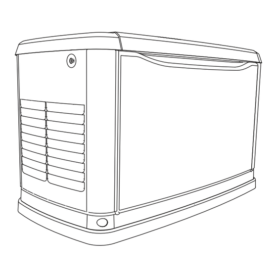
Page 10: The Generator
General Information The Generator 003603 Figure 2-1. Components and Control Locations Control Panel Oil Tank Sediment Trap AVR Filter Battery Compartment Oil Fill Cap/Oil dip Fuel Regulator (Battery not supplied) stick Main Line Circuit Breaker (Generator Exhaust Enclosure Oil Filter Fuel Inlet Disconnect) Data Plate Location... -
Page 11: Specifications
General Information Specifications Generator Model 15 kW EcoGen Rated Voltage Rated Maximum Load 62.5 Current (Amps) at 240 Volts (LP and NG)* Main Circuit Breaker 70 Amp Phase Rated AC Frequency 60 Hz Battery Requirement 12 Volts, Group 26R 540 CCA Minimum or Group 35AGM 650 CCA Minimum Unit Weight in Lbs. -
Page 12: Protection Systems
General Information Protection Systems The Emission Control System code is EM (Engine Modification). The Emission Control System on this The generator may need to run for long periods of time generator consists of the following: with no operator present to monitor the engine/generator System Components conditions. -
Page 13: Activating The Generator
General Information Activating the Generator The generator should be activated upon initial start-up. See the installation manual for complete instructions. Replacement Parts Description 15 kW EcoGen 26R Exide Battery 0H34215 Spark Plug 0G0767A Oil Filter 070185E Air Filter 0J8478 Control Panel Fuse... - Page 14 General Information This page intentionally left blank. Owner’s Manual for 60 Hz EcoGen™ Generators...
-
Page 15: Section 3: Operation
Operation Section 3: Operation Site Prep Verification 1. Cut the plastic bag to remove the keys. 2. Use the keys to open the lid of the generator. The generator must be installed so that airflow into and NOTE: The enclosed keys provided with this unit are out of the generator is not impeded. -
Page 16: Intake Side Panel Removal
Operation Intake Side Panel Removal 3. Lift the intake panel up and away from the generator. Figure 3-2. The intake side panel (A) must be NOTE: Always lift the intake side panel straight up removed to access the battery compartment, fuel before pulling away from enclosure. -
Page 17: Control Panel Interface
Operation Control Panel Interface Using the AUTO/OFF/MANUAL Interface Figure 3-5. The control panel interface (A) is located under the lid of the enclosure. Verify that both the left and right side locks are unlocked before attempting to lift the Button Description of Operation lid of the enclosure. -
Page 18: Menu System Navigation
Operation Menu System Navigation To get to the MENU, use the ESCAPE button from any page. You may need to press the ESCAPE button several times ↑ ↓ before reaching the MENU page. Navigate to the desired menu by using the buttons. - Page 19 Operation Current Date/Time UP ARROW = 02/14/13 07:40 ENTER DOWN ARROW = Run Hours (H) ENTER ENTER MAINT Run Hrs MAINT ENTER Maint. Log Scheduled Access Requires Password DEALER ENTER ENTER - 1 thru 50 + EXAMPLE: "Battery Maintained" Inspect Battery 200 RnHr or 12/27/13 "Schedule A Serviced"...
-
Page 20: Battery Charger
Operation Battery Charger • output continually optimized promote maximum battery life. NOTE: The battery charger is integrated into the control • charging levels are safe. module in all models. NOTE: A warning is displayed on the LCD when the The battery charger operates as a smart charger that battery needs service. -
Page 21: Section 4: Maintenance
Maintenance Performing Scheduled Maintenance Regular maintenance will improve performance and extend engine/equipment life. Generac Power Systems, It is important to perform maintenance as specified in the Inc. recommends that all maintenance work be Service Schedule for proper generator operation. Check... -
Page 22: Maintenance Log
Maintenance Service Schedule Schedule A Schedule B Every Every Three Every Every Service Weekly Months Year Two Years Four Years or 500 Hours or 1000 Hours Check Enclosure Louvers for Dirt and Debris Check AVR and Engine Filter Check Lines and Connections for Fuel or Oil Leaks ... -
Page 23: Checking Engine Oil Level
Maintenance Checking Engine Oil Level 2. Allow the generator to start and warm up for a few minutes. WARNING 3. Set the generator disconnect on the generator to ON (CLOSED). Risk of burns. Allow engine to cool before 4. The system is now operating in automatic mode. draining oil or coolant. -
Page 24: Changing The Oil And Oil Filter
Maintenance Changing the Oil and Oil Filter 001385 Figure 4-3. Exploded View – EcoGen Oil System Drain Pump Kit An Oil System Drain Pump Kit (P/N 0K3717) has been EcoGen Oil System Drain Pump Assembly shipped with this unit. Refer to the instructions included 1. -
Page 25: Ecogen Oil Change Procedure
Maintenance EcoGen Oil Change Procedure WARNING Skin irritation. Avoid prolonged or repeated contact with used motor oil. Used motor oil has been shown to cause skin cancer in laboratory animals. Thoroughly wash exposed areas with soap and water. (000210) 1. Place the MLCB to the OFF position. 2. -
Page 26: Replacing The Engine Air Filter
Maintenance 16. Screw the new oil filter on by hand until the filter 6. Install the air cleaner cover and cover clip. gasket contacts the oil filter adapter. Tighten the new oil filter ¾ to one full turn more. Replacing the AVR Filter 17. -
Page 27: Maintaining The Spark Plugs
Maintenance Maintaining the Spark Plugs 10. Install AVR filter housing. 11. Install front panel and lower the generator lid. Check and replace the spark plugs as necessary. WARNING Valve Clearance Adjustment Electrical shock. Do not disconnect spark Check the valve clearance after the first 25 hours of plug wires with engine running. -
Page 28: Adjust Valve Clearance
Maintenance 002380 001414 Figure 4-17. Valve Clearance Adjustment Figure 4-16. Remove AVR Fan Screws 6. Turn the pivot ball stud (D) using a 10 mm Allen 5. Remove spark plug cables from spark plug wrench while checking clearance between the terminals. -
Page 29: Battery Maintenance
Maintenance Battery Maintenance WARNING The battery should be regularly inspected per the Service Schedule. Contact an IASD for assistance if necessary. Proceed as follows to inspect the battery: (000137a) 1. Press the OFF button to shut down the generator, then lift the lid and remove the front panel. WARNING 2. -
Page 30: Attention After Submersion
Maintenance Remove From, and Return To Service Procedure Remove From Service If the generator will be out of service longer than 90 days, proceed as follows to prepare the generator for storage: 1. Start the engine and let it warm up. 2. - Page 31 Maintenance charge. Replace the battery if it will not maintain a charge. 4. Clean and wipe down the entire generator. 5. Verify that the 7.5 amp fuse is removed from the generator control panel. 6. Reconnect the battery. Observe battery polarity. Damage may occur if the battery is connected incorrectly.
- Page 32 Maintenance This page intentionally left blank. Owner’s Manual for 60 Hz EcoGen™ Generators...
-
Page 33: Section 5: Troubleshooting / Quick Reference Guide
Troubleshooting / Quick Reference Guide Section 5: Troubleshooting / Quick Reference Guide Generator Troubleshooting Problem Cause Correction Engine will not 1. Blown fuse. 1. Correct short circuit condition by replacing 7.5 crank. amp fuse in generator control panel. Contact an Independent Authorized Service Dealer (IASD) if fuse continues to blow. -
Page 34: Quick Reference Guide
Troubleshooting / Quick Reference Guide Quick Reference Guide To clear an active alarm, press the OFF button, the ENTER button, and then press AUTO. If the alarm reoccurs, contact an IASD. Active Alarm Problem Things to Check Solution FLASHING Unit running in AUTO but NONE Check MLCB. - Page 35 Troubleshooting / Quick Reference Guide Active Alarm Problem Things to Check Solution Unit will not start in Check the LEDs / UNDERSPEED AUTO with remote start Contact an IASD. screen for alarms. signal. Unit will not start in STEPPER Check the LEDs / AUTO with remote start Contact an IASD.
-
Page 36: Avr Troubleshooting
Troubleshooting / Quick Reference Guide AVR Troubleshooting Table 5-1. AVR Troubleshooting Ecode/Active Problem Things to Possible Causes/Solution Alarm Check 1048 VSCF Overload RED Unit shuts down Check the Alternator, AVR or wiring is damaged. during operation. LEDs/Screen Contact servicing dealer. for alarms. - Page 37 Troubleshooting / Quick Reference Guide Table 5-1. AVR Troubleshooting Ecode/Active Problem Things to Possible Causes/Solution Alarm Check 1057 VSCF Unit shuts down Check the Probable causes are: Overvoltage during operation LEDs/Screen 1) The generator has been overloaded. Remove load and or starting.
-
Page 38: Avr Diagnostics
Troubleshooting / Quick Reference Guide AVR Diagnostics Table 5-2. AVR Diagnostics Symptom Possible Causes Generator stalls when large load is Total load is too big for the generator. Loads must be less than 10 kW or 2 hp when supplied. operating under 3600 rpm.Contact installing dealer to correct installation. - Page 40 Part No. 0L6633 Rev. A 09/13/16 Generac Power Systems, Inc. ©2016 Generac Power Systems, Inc. All rights reserved S45 W29290 Hwy. 59 Specifications are subject to change without notice. Waukesha, WI 53189 No reproduction allowed in any form without prior written 1-888-GENERAC (1-888-436-3722) consent from Generac Power Systems, Inc.
Need help?
Do you have a question about the 15 kW EcoGen and is the answer not in the manual?
Questions and answers