Table of Contents
Advertisement
Advertisement
Table of Contents

Related Manuals for Fluid Imaging Technologies FlowCam 8000 series

Summary of Contents for Fluid Imaging Technologies FlowCam 8000 series
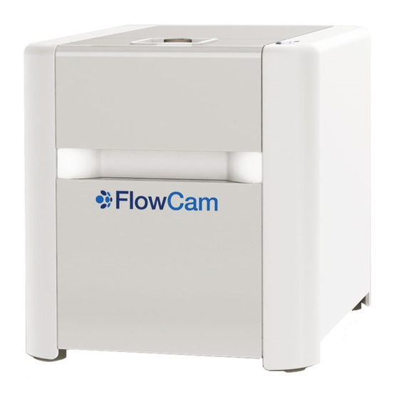
- Page 1 FlowCam 8000 Series ® Dynamic Imaging Particle Analyzer User Guide...
- Page 2 Fluid Imaging Technologies. Fluid Imaging Technologies may have patents or pending patent applications, trademarks, copyrights or other intellectual or industrial property rights covering this document or subject matter in this document.
-
Page 3: Table Of Contents
Appendix B: Frequently Asked Questions ................34 Appendix C: Services ......................35 Standard Factory Limited Warranty ..................37 Fluid Imaging Technologies FOV (Field-of-View) Flow Cell Limited Warranty ..........38 Customer Support ....................... 38 Declaration of Conformity ....................39 FlowCam® 8000 Series Dynamic Imaging Particle Analyzer... -
Page 4: Warnings
Warnings Before operating your FlowCam 8100 or 8400 analyzer, read this guide carefully to prevent damage to humans, animals, integrated devices, and connected devices. Always follow local safety rules. The instrument should be verified for safe operation following normal use, maintenance, and any factory service activities. - Page 5 Maximum operating altitude: 2000 meters Do not attempt any repairs yourself. Doing so will void your Standard Factory Limited Warranty. • If your FlowCam analyzer requires service, contact Fluid Imaging Technologies for additional instructions. FlowCam® 8000 Series Dynamic Imaging Particle Analyzer...
-
Page 6: Introduction
Introduction The FlowCam 8000 Series Dynamic Imaging Particle Analyzer combines selective capabilities of flow cytometry, microscopy, and fluorescence detection to rapidly evaluate particulate matter in a moving fluid. The FlowCam analyzer’s high-speed digital camera automatically counts, images, and characterizes the particles or cells in a sample. -
Page 7: Technical Specifications
Technical Specifications Optics Options 8100 8400 4X Flow Cell • Fused quartz • FOV300, 300 µm depth x 1500 µm width • FOV600, 600 µm depth x 1750 µm width 10X Flow Cell • Fused quartz • FOV80 • 80 µm depth x 700 µm width 20X Flow Cell •... -
Page 8: Analyzer Components
Analyzer Components Upper hatch with safety interlock Sample inlet port Fluid position sensor Flow cell Flow cell retainer thumbscrews retainer Objective Tubing shroud manifold Syringe Syringe pump valve manifold Lower door and bins for fluidics bottles FlowCam® 8000 Series Dynamic Imaging Particle Analyzer 8 of 39... -
Page 9: Overview
Overview The FlowCam 8100 and 8400 analyzers use dynamic imaging particle analysis to perform microscopic particle measurements rapidly enough to produce statistically significant amounts of particle data. The FlowCam analyzers gather numerous measurements for each particle, providing the detailed data needed for a thorough particle analysis. -
Page 10: Objectives
Objectives Objective lenses with varying magnification are used depending upon the application. As all optical systems have a specific focal depth of field (DOF), it is important to select an appropriate objective/flow cell combination to optimize image collection. Objective Flow Cell 300FOV, 600FOV 80FOV 50FOV... -
Page 11: Welcome
Ensure that there is no damage to the packing materials or equipment inside. If anything has been damaged or is missing, contact Fluid Imaging Technologies or your local distribution representative immediately. Be sure to save the white shipping container that your FlowCam analyzer came in. -
Page 12: Setting Up The Analyzer
Setting Up the Analyzer Connecting Peripherals Connection ports are on the back of the FlowCam analyzer. Two USB3 Two Ethernet VGA port ports ports Audio in Two RS-232 serial ports Audio out Microphone in HDM1 port DVI port Four USB2 ports 1. -
Page 13: Preparing The Analyzer
Preparing the Analyzer Checking Internal Connections Open the upper hatch and lower door on the analyzer and inspect all of the tubing connections to ensure they are in place and secure. • Check the inlets from the rinse and cleaner bottles into the system. Check the waste tubing connection from the pump to the waste container. -
Page 14: Installing The Flow Cell
Installing the Flow Cell The flow cell is a high-precision optical component. Great care is taken during its manufacture to ensure conformance to exacting tolerances. The polished optical faces undergo dozens of inspections to ensure uniformity, from the certification of raw materials to the matching of the finished cells. •... -
Page 15: Installing The Objective Lens
To install the flow cell: 1. Open the upper hatch and lower door of the FlowCam analyzer. Sample inlet port 2. Loosen the flow cell retainer’s two red thumbscrews and remove it. Upper 3. With the flow cell’s serial number tubing toward you, connect the upper tubing attached to the flow cell to... - Page 16 Note: When changing the objective lens from one magnification to another, you must also change the pump syringe. See Appendix A for more information. Objective shroud Objective lens Objective stage To install an objective lens: 1. Open the analyzer’s upper hatch and pull the silver knob to open the objective shroud. 2.
-
Page 17: Autofocusing The Flow Cell
Autofocusing the Flow Cell The FlowCam analyzer’s autofocus feature focuses the optical system algorithmically without operator intervention, ensuring repeatable focus position and, therefore, measurements. To focus the flow cell, you need the Fluid Imaging focusing standard (Autofocus Beads), other bead standards, or the sample you will be analyzing. - Page 18 2. If necessary, align the flow cell to the correct position using the positioning knob located to the left of the flow cell assembly in the interior of the analyzer. The flow cell can be moved left and right. Note: The red lines need to be positioned within the gray lines, which represent the walls of the flow cell.
-
Page 19: Focusing The Flow Cell Manually
8. Close the Setup and Focus Mode window. You are now ready to begin analyzing samples. Note: You only need to perform the autofocus routine upon initial startup, and after you change the flow cell or the objective lens. Otherwise, you can use the manual focus process to adjust the focus of individual samples. - Page 20 2. If necessary, align the flow cell to the correct position using the positioning knob located to the left of the flow cell assembly in the interior of the analyzer. The flow cell can be moved left and right. Note: The red lines need to be positioned within the gray lines, which represent the walls of the flow cell.
- Page 21 6. Enter a flow rate (for example, 1), click Set, and then click the Start Pump button to draw the sample down into the flow cell. 7. As the sample flows, focus the view by clicking the left and right green arrows on the Setup and Focus Mode window until the edges of the particles become clear.
-
Page 22: Defining The Context Settings
Defining the Context Settings 1. On the toolbar, click the Context tool. FlowCam 8100 toolbar FlowCam 8400 toolbar 2. The Context dialog opens. The Context dialog contains the settings used by the FlowCam analyzer to capture particles of interest during a sample analysis. This includes settings for the camera, fluorescent thresholds and gains, and other various parameters. - Page 23 5. The Capture tab lets you set specific parameters for capturing particles, such as: • Distance to Nearest Neighbor—Any particles that are equal to or less than this distance in microns from each other will be imaged as one particle. •...
- Page 24 7. The Fluidics tab is where you define the sample volume, flow rate, autoimage rate, efficiency, run time, priming type, and sample dilution parameters. Note: The machine prime option uses the built-in functionality of the fluid position sensor. 8. The Filter tab lets you select an image filter (ESD, ABD, none, advanced) and set its minimum and maximum diameter values to specify the size range of the particles of interest to save.
- Page 25 9. The Reports tab provides options for exporting and printing reports when an analysis finishes, as well as options for performing classification. 10. The Notes tab provides a space to enter comments about the sample analysis. These notes are saved as a text file in the sample run data folder. The filename begins with the List filename appended with _notes.txt.
- Page 26 13. (FlowCam 8400 analyzer only) The Fluorescent Measurement Settings tab is where you set thresholds for particle acquisition and rejection. 14. Click OK to save your context settings. FlowCam® 8000 Series Dynamic Imaging Particle Analyzer 26 of 39...
-
Page 27: Performing A Sample Analysis
Performing a Sample Analysis Before sample analysis, perform the following steps: • Check the fluidics bottles. Fill the cleaner and rinse bottles, if necessary, and empty the waste bottle. • If necessary for the particular sample, change the flow cell. •... -
Page 28: Cleaning And Rinsing The Analyzer
Cleaning and Rinsing the Analyzer After analysis, clean and rinse the system to remove any leftover particles—using the pump’s flush feature or performing a manual cleaning and rinsing. Flush the System 1. Select Setup> Pump from the menu bar. The Pump Controller dialog opens. 2. - Page 29 2. Select the Run at end of analysis checkbox for the Clean option. 3. Click the Number of cycles to perform drop-down list and select the desired number of clean cycles. Note: You cannot run the clean function without also running the rinse function. 4.
-
Page 30: Care And Maintenance
Care and Maintenance General Immediately after use, rinse the analyzer system with appropriate cleaner. This rinse will help keep the flow cells clear and free from contamination for day-to-day use. If necessary, precede the rinse with a solvent or surfactant to remove particles. Flow Cell •... -
Page 31: Appendix A: Changing The Pump Syringe
Appendix A: Changing the Pump Syringe The FlowCam analyzer has three pump syringes that accommodate the three objective lenses. Objective Lens Power Pump Syringe Size 5 mL 1 mL 0.5 mL 5-mL pump syringe Plunger Syringe pump Syringe Plunger lock screw Plunger base FlowCam®... - Page 32 To change the pump syringe: 1. Select Setup> Pump from the menu bar. The Pump Controller dialog opens. 2. Click the Change button under the Syringe options. 3. A message asks if you want to change the syringe. Click Yes, and follow the onscreen prompts. 4.
- Page 33 8. The Select Syringe Size dialog appears. Select the applicable size from the Syringe Size drop- down list and click OK. 9. Clean the previous syringe and replace it in its container. Tip: Remove the plunger from the syringe casing to thoroughly clean the syringe. FlowCam®...
-
Page 34: Appendix B: Frequently Asked Questions
Appendix B: Frequently Asked Questions Q. How do I clean a clogged flow cell? A. Flow cell handling and cleaning instructions were shipped with your instrument. If you did not receive these instructions, contact a member of our customer support team to order your flow cell cleaning and maintenance kit. -
Page 35: Appendix C: Services
VisualSpreadsheet software upgrade for the FlowCam analyzer and one satellite license • A preventive maintenance service conducted at your site includes a half-day refresher training session with a Fluid Imaging Technologies technician. FlowCam® 8000 Series Dynamic Imaging Particle Analyzer 35 of 39... - Page 36 Installation and Operational Qualification An installation and operational qualification (IOQ) service is performed when the instrument must be qualified for use. IOQs occur either during initial receipt of a FlowCam analyzer or after it is relocated within a company property. •...
-
Page 37: Standard Factory Limited Warranty
Standard Factory Limited Warranty Fluid Imaging Technologies, Inc. (the “Seller”) warrants that the FlowCam product (the “Product”) purchased by you (the “Customer”) shall be free from material defects in workmanship and material for a period of one year from the date of shipment by the Seller (the “Limited Warranty”); provided, however, that the Limited Warranty does not cover any consumables (flow cells, flow cell holders, or tubing) or third-party manufactured/customer purchased items incorporated in the Product. -
Page 38: Fluid Imaging Technologies Fov (Field-Of-View) Flow Cell Limited Warranty
This warranty is an amendment to the Fluid Imaging Technologies Standard Factory Limited Warranty. Fluid Imaging Technologies, Inc. (the “Seller”) will repair or, at its option, replace, without charge, your FOV flow cell (the “Product”) if it proves to be defective in material or workmanship under normal use during the warranty period. -
Page 39: Declaration Of Conformity
Product: FlowCam Particle Analyzer Model Numbers: 8100, 8400 The undersigned hereby declares, on behalf of Fluid Imaging Technologies, Inc. of Scarborough, Maine, that the above-referenced product, to which this declaration relates, is in conformity with the provisions Council Directive 2004/22/EC (December 15, 2004) on Measuring Instruments •...