Table of Contents
Advertisement
Advertisement
Table of Contents

Summary of Contents for Astronics OmniBusII
- Page 1 OmniBus II PCIe/PXIe USER'S MANUAL INTERFACE CARD to AVIONICS DATABUSES February 6, 2015 Rev. B0 Copyright 2014-2015 Ballard Technology, Inc. Astronics Ballard Technology Phone: +1.425.339.0281 800.829.1553 Email: support@ballardtech.com www.ballardtech.com MA203-20150206 Rev. B0...
- Page 3 Molex Inc. Windows® is a registered trademark of Microsoft Corporation. Ballard Technology®, OmniBus® and CoPilot® are registered trademarks of Ballard Technology, Inc. BTIDriver™ is a trademark of Ballard Technology, Inc. All other product names or trademarks are property of their respective owners. Astronics Ballard Technology Phone: +1.425.339.0281 800.829.1553 Email: support@ballardtech.com...
-
Page 5: Table Of Contents
TABLE OF CONTENTS 1. INTRODUCTION 1.1 OmniBus II Overview ..................1-1 1.2 OmniBus II Configurations ................1-3 1.3 Avionics Databus Protocols ................1-4 1.4 Other Documentation ..................1-4 1.5 Support and Service ................... 1-5 1.6 Updates ....................... 1-5 2. INSTALLATION 2.1 Step 1: Insert the Card into the System .............. - Page 6 TABLE OF CONTENTS 6.3.1 Software-Selectable Bus Termination ............6-2 6.3.2 Configurable RT Response Time ..............6-3 6.3.3 Variable Transmit Amplitude ................ 6-3 6.3.4 Zero Crossing Distortion ................6-3 6.4 ARINC 429 Modules ..................6-4 6.4.1 Parametric Waveform ..................6-5 6.4.2 Configurable Frequency ................6-5 6.4.3 Output State ....................
- Page 7 TABLE OF CONTENTS LIST OF FIGURES Figure 1.1—OmniBus II PCIe card ................1-1 Figure 1.2—OmniBus II PXIe card ................1-2 Figure 1.3—The two-core architecture of OmniBus II PCIe/PXIe card ......1-3 Figure 2.1—PXIe Compatible Chassis Glyphs ............... 2-2 Figure 3.1—Sample CoPilot screen ................3-1 Figure 4.1—Built-in test and System monitor architecture ..........
- Page 8 TABLE OF CONTENTS This page intentionally blank. OmniBus II PCI /PXIe User’s Manual...
-
Page 9: Introduction
1. INTRODUCTION This manual is the user’s guide for PCIe® and PXI™ Express models of Ballard Technology’s OmniBus® II family of products. Throughout this manual any reference to the PCIe card applies to the OmniBus II PCIe card, reference to the PXIe card applies to the OmniBus II PXIe card, and references to OmniBus and OmniBus II apply generically to all the products in the designated family. -
Page 10: Figure 1.2-Omnibus Ii Pxie Card
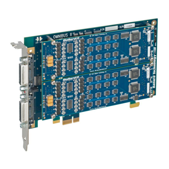
INTRODUCTION Figure 1.2—OmniBus II PXIe card The high-density modular design of the OmniBus family provides flexibility that enables the user to select from many protocol, platform, and channel count com- binations. Each OmniBus product can have at least two modules, and each mod- ule has its own circuitry to handle the channels and protocols associated with it. -
Page 11: Omnibus Ii Configurations
INTRODUCTION Avionics Avionics Databuses Databuses Protocol Protocol Module Module Core A Core B SDRAM SDRAM FPGA FPGA Flash Flash 1:2 PCIe Switch 1 Lane PCIe PCIe Connector Figure 1.3—The two-core architecture of OmniBus II PCIe/PXIe card The easiest way to operate OmniBus products is with CoPilot®, Ballard Tech- nology’s databus analyzer and simulation software. -
Page 12: Avionics Databus Protocols
INTRODUCTION For future reference, we encourage you to record the assembly part number and serial number of your OmniBus product. You may wish to use the space provided below: Assembly PN: ________ - ________ - ________ (Board PN) (Core A PN) (Core B PN) Serial No: __________________ 1.3 Avionics Databus Protocols... -
Page 13: Support And Service
INTRODUCTION The software distribution disk accompanying the OmniBus has example pro- grams, drivers, and driver installation instructions for various operating systems, and other information, files, and resources. 1.5 Support and Service Ballard Technology offers technical support before and after purchase. Our hours are 9:00 to 5:00 Pacific Time, though support and sales engineers are... - Page 14 INTRODUCTION This page intentionally blank. OmniBus II PCIe/PXIe User’s Manual...
-
Page 15: Installation
2. INSTALLATION This chapter explains the procedures for installing an OmniBus II PCIe/PXIe card. There are four steps to installation: Step 1: Insert the Card into the System Step 2: Install the Driver Software Step 3: Set the Card Number and Test the Installation Step 4: Connect to Databus(s) I/O After the installation steps are completed, the PCIe/PXIe card is ready to communicate on the databus(es). -
Page 16: Step 2: Install The Driver Software
INSTALLATION For a PXIe System: • Shut down the system. • On the card, select the required clock by sliding the on-board switch left or right. • With the injector handle in the down position, insert the card into an empty chassis slot marked with one of the following PXIe Chassis Glyphs: * replaced with chassis slot number... -
Page 17: Step 3: Set The Card Number And Test The Installation
INSTALLATION 2.3 Step 3: Set the Card Number and Test the Installation You must set a card number on the controlling computer for software to uniquely identify each PCIe card. Since many Ballard BTIDriver™-compliant hardware devices (e.g., OmniBus II PCIe/PXIe cards) can be concurrently connected to the same computer, software running on a given computer uses a unique card number to designate which hard- ware device is being accessed. - Page 18 INSTALLATION This page intentionally blank. OmniBus II PCIe/PXIe User’s Manual...
-
Page 19: Operation
3. OPERATION Software is used to control OmniBus products and to manipulate data. Whether you use Ballard’s CoPilot® software or develop your own applications using Ballard’s BTIDriver™ API library, it is easy to operate the PCIe/PXIe card and to utilize its powerful interface. 3.1 CoPilot A PC with CoPilot and Ballard’s OmniBus II PCIe/PXIe card makes a powerful, low-cost databus analyzer/simulator. -
Page 20: User-Developed Software
OPERATION Because CoPilot can host multiple channels and databus protocols in the same project, it is the ideal tool for operating OmniBus products. CoPilot can be pur- chased separately or with an OmniBus product. For more information or a free evaluation copy, call Ballard at (800) 829-1553. -
Page 21: Omnibus Ii Features
4. OMNIBUS II FEATURES This section describes special capabilities and interface signals available on many OmniBus II products. Some of these features (such as IRIG time) are on all mod- els and others (such as avionics discretes) are only on a subset. If you need more information than is presented here, please contact Customer Support at Ballard Technology for assistance (see Section 1.5). -
Page 22: Irig Timer
OMNIBUS II FEATURES hardware and host communication. Initiated test resets the card and is not in- tended to be performed while the card is configured or running. 4.2.3 Continuous Built-in Test (CBIT) During card operation, dedicated hardware constantly monitors multiple internal modules for errors. -
Page 23: Core Discretes
OMNIBUS II FEATURES There are a number of formats for IRIG timing. The OmniBus II family uses the IRIG formats indicated in Table 4.1. The characteristics of the external electrical interface to the IRIG pins are as shown in Table 4.2 and Table 4.3. 1000 pps Format 100 pps... -
Page 24: Avionics Discretes
OMNIBUS II FEATURES an output, the status of a core discrete output can be verified by reading the input. At power on all core discrete outputs are tristated and are enabled by writing to the output or by explicitly enabling it. Ballard’s BTIDriver API provides functions to read, write, and enable (tristate) core discretes. -
Page 25: Shunt Inputs
OMNIBUS II FEATURES 4.5.1 Shunt Inputs A shunt input circuit pin is pulled up to a voltage source through a resistor. A load resistance applied between the pin and ground will shunt current from the source and generate a voltage at the pin. The pin voltage is compared with a ref- erence voltage for input state detection. -
Page 26: Shunt Output Considerations
OMNIBUS II FEATURES Figure 4.3—OmniBus II Discrete Shunt Output Circuit 4.5.4 Shunt Output Considerations Limits: The OmniBus II discrete shunt outputs are open-ground switches capable of sinking up to 200mA. The discrete outputs can withstand up to 35 VDC and are capable of interfacing with industry standard avionics discrete signals. -
Page 27: Shunt Discrete Input/Output Usage
OMNIBUS II FEATURES 4.5.5 Shunt Discrete Input/Output Usage Ballard Technology’s BTIDriver API provides functions to read and write the discretes. The parameter dionum in the API functions (BTICard_ExtDIORd and BTICard_ExtDIOWr) specifies which discrete to read or write. Table 4.6 below shows the correlation between dionum and its hardware refer- ence designator (i.e., ADIOn). - Page 28 OMNIBUS II FEATURES This page intentionally blank. OmniBus II PCIe/PXIe User’s Manual...
-
Page 29: Omnibus Ii Pxie Specific Features
5. OMNIBUS II PXIE SPECIFIC FEATURES This chapter describes features available only on OmniBus II PXIe products. OmniBus II PXIe is a Type 2 Compact PCI Express (cPCIe) card with eXtensions for Instrumentation (PXIe). As such, PXIe cards can be used in either cPCIe or PXIe systems. -
Page 30: Pxie Trigger Access
OMNIBUS II PXIE SPECIFIC FEATURES 5.2 PXIe Trigger Access The following table shows the PXIe Trigger signals supported by the OmniBus II PXIe card. All signals are asynchronous to either CLK10 or CLK100. PXIe Trigger signals accessed through BTICard_ExtDIORd, BTICard_ExtDIOWr, and BTICard_ExtDIOEnWr functions by passing in the associated dionum per Table 5.1. -
Page 31: Table 5.2-Pxie Trigger To Protocol Trigger Mapping
OMNIBUS II PXIE SPECIFIC FEATURES Refer to Table 5.3 for mappings between protocol syncs (Sync A-C) and PXIe Triggers (PXI*). Protocol Trigger PXIe Signal Trigger Mask Parameter PXI_TRIG[0] TRIGMASK_PXITRIGA PXIe_DSTARA TRIGMASK_PXISTARA PXI_TRIG[1] TRIGMASK_PXITRIGB PXIe_DSTARB TRIGMASK_PXISTARB PXI_TRIG[2] TRIGMASK_PXITRIGC PXI_STAR TRIGMASK_PXISTARC Table 5.2—PXIe Trigger to Protocol Trigger Mapping Protocol Sync PXIe Signal Sync Mask Parameter... -
Page 32: Pxie Status
OMNIBUS II PXIE SPECIFIC FEATURES The OmniBus II PXIe also extends the protocols’ TriggerDefine function capabilities by adding transitional trigger parameters. These new parameters allow the protocol to be triggered on a high, low, rising, or falling state of the assigned protocol trigger (A-C). -
Page 33: Chassis Slot Glyph
OMNIBUS II PXIE SPECIFIC FEATURES 5.5 Chassis Slot Glyph The PXIe card can be installed in a “PXI Express Hybrid Slot”, a “PXI Express Peripheral Slot”, or a “PXI Express System Timing Slot”. These slot types will be marked on the system chassis with one of the three Glyphs from * replaced with chassis slot number . - Page 34 OMNIBUS II PXIE SPECIFIC FEATURES This page intentionally blank. OmniBus II PCIe/PXIe User’s Manual...
-
Page 35: Module Configurations
6. MODULE CONFIGURATIONS OmniBus modules are available for many different protocols, including MIL-STD-1553, ARINC 429/575, ARINC 708/453, and ARINC 717/573. Other standard and custom modules are available. This chapter lists the part numbers for PCIe/PXIe cards and for MIL-STD-1553, ARINC 429/717, and ARINC 708 I/O modules and describes the features and functionality of each. -
Page 36: Software-Selectable Bus Termination
MODULE CONFIGURATIONS Part No. CH0 Level CH1 Level – – – S = Single function M = Multifunction P = Multifunction with parametrics Table 6.3—MIL-STD-1553 Module Part Numbering Each MIL-STD-1553 channel is available in three levels of functionality (sum- marized in the table below). All levels provide at least single terminal Bus Con- troller, Remote Terminal, and Monitor operation and user-configurable RT response time. -
Page 37: Configurable Rt Response Time
MODULE CONFIGURATIONS 6.3.2 Configurable RT Response Time The RT response time of MIL-STD-1553 OmniBus modules may be individually set in software for each 1553 channel. The response time is measured from the mid-bit zero crossing of the parity bit to the mid-bit zero crossing of the status word. -
Page 38: Arinc 429 Modules
MODULE CONFIGURATIONS 6.4 ARINC 429 Modules The preferred ARINC 429 I/O modules for OmniBus II are listed in the table below. Each channel of those marked as “selectable” in the table can be config- ured as either a receiver or a transmitter. Parametric Configurable Output... -
Page 39: Parametric Waveform
MODULE CONFIGURATIONS 6.4.1 Parametric Waveform OmniBus II ARINC 429 modules with parametric waveform capability provide control over transmit amplitude, offset and null voltages, rise time, and fall time. The amplitude, offset and null voltages are controlled by specifying the high, null, and low voltages of the differential waveform. -
Page 40: Arinc 708 Modules
MODULE CONFIGURATIONS 6.5 ARINC 708 Modules The table below lists the I/O modules available with ARINC 708 channels Part No. 708 Channels Parametrics 1R/1T – 2R/2T – 1R/1T Amplitude 2R/2T Amplitude R = receive and T = transmit Table 6.10—MIL-STD-1553 Module Part Numbering ARINC 708 modules are available with one receiver and one transmitter or two receivers and two transmitters. -
Page 41: Arinc 717 Modules
MODULE CONFIGURATIONS configval Constant Description Select all default settings (bold below) PARAMCFG708_DEFAULT PARAMCFG708_AMPLON Enables parametric amplitude control Enables parametric amplitude control high range PARAMCFG708_AMPLHI PARAMCFG708_AMPLLO Enables parametric amplitude control low range PARAMCFG708_AMPLOFF Disables parametric amplitude control Table 6.11—ARINC 708 ParamAmplitudeConfig Configval Since the actual amplitude and linearity depend on both the line driver and load, the user must calibrate with the conditions in use for the degree of accuracy desired. - Page 42 MODULE CONFIGURATIONS This page intentionally blank. OmniBus II PCIe/PXIe User’s Manual...
-
Page 43: Connector Pinouts
7. CONNECTOR PINOUTS The standard connector on OmniBus II products is a 60-pin Molex® LFH™ re- ceptacle. Each OmniBus module (core) has an LFH connector dedicated to it. Signals on the LFH connector are either general-purpose or module-specific. General-purpose signals (including triggers, syncs, discretes, and timing) are common to most modules and protocols. -
Page 44: Module-Specific Wiring
CONNECTOR PINOUTS Pair # LFH Pin Name Pair # LFH Pin Name BUS0N BUS8N BUS0P BUS8P BUS2N BUS10N BUS2P BUS10P BUS4N BUS12N BUS4P BUS12P BUS6N BUS14N BUS6P BUS14P CDIO0 CDIO3 CDIO4 CDIO7 CGND CGND NC/5VA NC/5VA IRIG RSVD CDIO5 CDIO6 CDIO1 CDIO2 BUS7P... -
Page 45: Mil-Std-1553
CONNECTOR PINOUTS 7.3.1 MIL-STD-1553 The pin assignments for the MIL-STD-1553 modules are listed in Table 7.2 be- low. Be sure to follow the coupling and termination guidelines provided in Appendix A. Used on Modules 16036 5x1 to 5x5 Name Description Pair # Name CH0AD... -
Page 46: Arinc 429
CONNECTOR PINOUTS 7.3.2 ARINC 429 The pin assignments for OmniBus ARINC 429 modules are listed in Table 7.3 below. Note: Module 455 in the table below also includes ARINC 717 chan- nels. See 7.3.4 for pinouts of the 717 channels on this module. 454/455* 16036 Channel... -
Page 47: Table 7.4-Pinouts For Arinc 708 Modules
CONNECTOR PINOUTS coupling and termination guidelines provided in Appendix A. Direct coupling is standard for ARINC 708, but transformer coupling is possible. Used on Modules LFH LFH 16036 810/820 811/822 Description Pair # Pin Name BUS A direct coupled (+) P2-2 BUS1P BUS A direct coupled (–) -
Page 48: Arinc 717
CONNECTOR PINOUTS 7.3.4 ARINC 717 The pin assignments for the ARINC 717 modules are listed in Table 7.5 below. All ARINC 717 channels can be either biphase or bipolar. Note: Module 455 in the table below also includes ARINC 429 chan- nels. -
Page 49: Standard Cables
CONNECTOR PINOUTS 7.4 Standard Cables Ballard sells a number of different cables that are useful for wiring to OmniBus II products. Each cable has a standard length. Non-standard lengths may be speci- fied by adding a /xx suffix after the part number, where xx is the length in feet. For example, a 16036/10 is a ten-foot-long 16036. -
Page 50: Table 7.6-Wiring Chart For 16036 Cable Assembly
CONNECTOR PINOUTS From From P2 Pair # P1 pin P2 pin Name P3 Pair # P1 pin P3 pin Name BUS0P BUS8P BUS0N BUS8N BUS1P BUS9P BUS1N BUS9N BUS2P BUS10P BUS2N BUS10N BUS3P BUS11P BUS3N BUS11N BUS4P BUS12P BUS4N BUS12N BUS5P BUS13P BUS5N... -
Page 51: Mil-Std-1553 Cable Assemblies
CONNECTOR PINOUTS 7.4.3 MIL-STD-1553 Cable Assemblies Ballard offers four standard cable assemblies for MIL-STD-1553 (see Table 7.7 below). The standard length is three feet. Cable Assy. No. No. of Ch. D-Sub 16037 16038 – 16039 – 16041 – – Table 7.7—MIL-STD-1553 cable assembly configurations These four cables are available for single or dual channel modules and with or without a D-sub connector. -
Page 52: Table 7.9-D-Sub Connector Pinout For Cable Assemblies 16037 And 16039
CONNECTOR PINOUTS The 25-pin female D-subminiature connector provides IRIG and discrete signals, as shown in Table 7.9. Consequently, the recommended cable assemblies are 16037 for dual-channel and 16039 for single-channel MIL-STD-1553 OmniBus modules. From Pair Name LFH Pin DB25S Pin CDIO0 CDIO1 CDIO2... -
Page 53: Appendix Acoupling And Termination
APPENDIX A COUPLING AND TERMINATION Coupling and termination only apply to OmniBus modules for MIL-STD-1553 and ARINC 708. Electrically, these databuses have similar characteristics. Ex- cept where a protocol is specified, the following discussion applies to both. A.1 Bus Termination The main databus consists of a pair of twisted, shielded wires with a characteris- tic impedance in the range of 70 to 85 ohms. -
Page 54: Figure A.1-Transformer Coupling To A Dual-Redundant Databus
COUPLING AND TERMINATION Figure A.1—Transformer coupling to a dual-redundant databus OmniBus II PCIe/PXIe User’s Manual... -
Page 55: Figure A.2-Direct Connection To A Dual-Redundant Databus
COUPLING AND TERMINATION Bus B 78Ω 78Ω T ERMINAT ORS BT P/N 17001 T EE ADAPT ERS BT P/N 17002 Bus A 78Ω 78Ω S T UB S T UB UNIT UNDER T ES T T RANS CEIVER T RANS CEIVER T erminal Figure A.2—Direct connection to a dual-redundant databus OmniBus II PCIe/PXIe User’s Manual... - Page 56 COUPLING AND TERMINATION This page intentionally blank. OmniBus II PCIe/PXIe User’s Manual...
-
Page 57: Appendix Brevision History
APPENDIX B REVISION HISTORY The following revisions have been made to this manual: Rev. A Date: March 27, 2014 Initial release of this manual. Rev. B0 Date: Februrary 6, 2015 Added updates for OmniBus II PXIe OmniBus II PCIe/PXIe User’s Manual... - Page 58 REVISION HISTORY This page intentionally blank. OmniBus II PCIe/PXIe User’s Manual...
Need help?
Do you have a question about the OmniBusII and is the answer not in the manual?
Questions and answers