Sign In
Upload
Download
Table of Contents
Contents
Add to my manuals
Delete from my manuals
Share
URL of this page:
HTML Link:
Bookmark this page
Add
Manual will be automatically added to "My Manuals"
Print this page
×
Bookmark added
×
Added to my manuals
Manuals
Brands
SafetySpeed Manuals
Sander
3760
Owner's manual
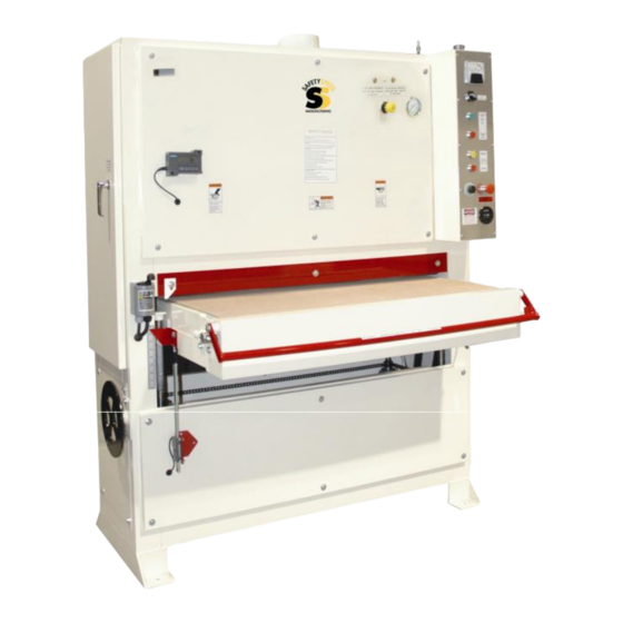
SafetySpeed 3760 Owner's Manual
Wide belt sander
Hide thumbs
1
Table Of Contents
2
3
4
5
6
7
8
9
10
11
12
13
14
15
16
17
18
19
20
21
22
23
24
25
26
27
28
29
30
31
32
33
34
35
36
37
38
39
40
41
42
43
44
45
46
47
48
49
50
51
52
53
54
55
56
57
58
59
60
61
page
of
61
Go
/
61
Contents
Table of Contents
Troubleshooting
Bookmarks
Table of Contents
Table of Contents
Warranty
Safety Information
Proposition 65 Warning
Set up
Electrical Service Requirements
Single Phase
Three-Phase Electrical Service (230V)
Air Service
Dust Collection
Introduction to the Components
Load Meter
Air Control
Sanding Heads Start Control
Sanding Head Stop Control
Emergency Stop Locations
Conveyor Table Speed Adjustment Controls
Conveyor Table Height Adjustment Gauges
Gauge with Ruler and Indicator
Simple Stationary Pointer
Optional Digital Positioning Gauge System
Abrasive Belt Tracking System
Introduction to the Components
Sanding Operations
Operational Checklist
Abrasive Sanding Belt General Information
Abrasive Sanding Belt Installation
Operating the Machine
Introduction to the Platen
37" X 60" Model Platen
Installing and Using the Platen
4375 Series Models Platen
Platen Removal 4375
Maintenance
Repairs
Lubrication
Sanding Head Rollers
Conveyor Table Rollers
Bronze Bushings
Jack Screws
Conveyor Drive Gear Reducer
Swing Arm Top Idler Roller
All Metal Moving Parts
Drive Motor Belt Tension
Platen Graphite Replacement
Platen Felt Replacement
Contact Roller Resurfacing
Contact Roller Removal/Replacement
Contact Roller Reinstallation
Re-Leveling the Contact Roller
Pinch Roller and Idler Roller Replacement
Rear Idler Roller Leveling
Level the Table
Level the Conveyor Table
Wide Belt Sander Belt Tracking
Maintenance
Trouble Shooting
Machine will Not Start
Unwanted Surface Marks
Sanding Belt Tracking
Exploded Views and Parts List
4375 Exploded Views and Parts
3760 Exploded Views and Parts
Electrician Wiring Schematics
Single Phase Wiring Schematic
Exploded Views and Parts List
Three Phase Wiring Schematic
Advertisement
Quick Links
1
Air Control
2
Wide Belt Sander Belt Tracking
Download this manual
Wide Belt Sander
Owner's Manual
Model 3760
Model 4375
Safety Speed Manufacturing
13943 Lincoln Street NE
Ham Lake, MN 55304
Tel: 763-755-1600 Fax: 763-755-6080
www.safetyspeed.com
sales@safetyspeed.com
Table of
Contents
Previous
Page
Next
Page
1
2
3
4
5
Advertisement
Table of Contents
Need help?
Do you have a question about the 3760 and is the answer not in the manual?
Ask a question
Questions and answers
Related Manuals for SafetySpeed 3760
Sander SafetySpeed 4375 Owner's Manual
Wide belt sander (61 pages)
This manual is also suitable for:
4375
Table of Contents
Print
Rename the bookmark
Delete bookmark?
Delete from my manuals?
Login
Sign In
OR
Sign in with Facebook
Sign in with Google
Upload manual
Upload from disk
Upload from URL


Need help?
Do you have a question about the 3760 and is the answer not in the manual?
Questions and answers