
Related Manuals for Eskon EPA300


Summary of Contents for Eskon EPA300
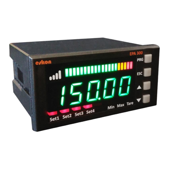
- Page 1 EPA300 PROCESS CONTROL DEVICE USER MANUAL Techniquip Ltd., Taunton, Somerset, TA2 6RN Tel 01823-351255 eMail sales@technquip.co.uk...
-
Page 2: Table Of Contents
1. INDEX INDEX ------------------------------------------------------------------------------------ 2 CONNECTIONS ------------------------------------------------------------------------- 3 FRONT PANEL DEFINITIONS ------------------------------------------------------- 5 SETUP ------------------------------------------------------------------------------------ 6 CONNECTION TO SENSOR DEVICE ------------------------------------------------------------------ 6 DEVICE CALIBRATION ---------------------------------------------------------------------------------- 7 ENTER RELAY SET VALUE ----------------------------------------------------------------------------- 8 OPERATING MODE: FUNCTIONS ------------------------------------------------- 10 Tare Function ------------------------------------------------------------------------------------------ 10 Viewing the Maximum and Minimum Reading Values -------------------------------------- 10 Changing Quick Set Values ------------------------------------------------------------------------- 10 Transition to Programming Mode ---------------------------------------------------------------- 10... -
Page 3: Connections
2. CONNECTIONS 1. Relay Output OUT-1 2. Relay Output OUT-2 Shown in tables below with pin 3. Relay Output numbers assigned. OUT-3 4. Relay Output OUT-4 Supply Voltage 24 VAC / DC or 85 / 265 VAC Digital Comn. RS485 RS232 USB HID USB CONNECTOR... - Page 4 5. Make sure that is shielded cables between device and sensor. 6. Do not leave the device exposed to a heat source (solar, heater etc.) 7. EPA300 industrial control device is not suitable for use in the external environment, Use only room conditions.
-
Page 5: Front Panel Definitions
3. FRONT PANEL DEFINITIONS 1) PRG ( ): Programming and Enter key. It is used to enter the menus or confirm the entered values. 2) ESC ( ): Escape, exit and backspace key. It is used to return to the upper menu or to exit the menus. -
Page 6: Setup
4. SETUP 4.1 CONNECTION TO SENSOR DEVICE Potentiometer connections: Connections of 4-20mA or 0-10 V sensors:... -
Page 7: Device Calibration
3.33 mV / V Ratiometric Sensor connections: 4.2 DEVICE CALIBRATION Your device is calibrated automatically according to factory settings and operates in the 0-100 value range. That is, the smallest reading on the sensor shows 0 on the screen and 100 on the screen. You can change this scale from the calibration menu. Use S-LO for the minimum value that will be shown on the screen, S-HI for the maximum value. -
Page 8: Enter Relay Set Value
After specifying the S-LO value, you can do the same for the S-HI value. 4.3 ENTER RELAY SET VALUE Set the SET values for the relay outputs of your device to be activated. For SET-1 value: (Keep it pressed) ... - Page 9 3. Set the SET-3 value for Relay output: (Keep it pressed) . Press and hold the UP and DOWN When PRG key is The decimal point pressed and entered, starts flashing. Use the keys to move to the next step. To UP and DOWN keys to enter a negative (-) value, press the value input screen...
-
Page 10: Operating Mode: Functions
5. OPERATING MODE: FUNCTIONS Your EPA300 process controller operates in two different modes. Your device is in 'operating mode' while the initial value of the sensor readout is displayed; In the 'programming mode' on the screen where the settings are changed and the parameters are changed. - Page 11 Press and hold PRG until OUT appears in the display. To return to the operating mode, press the ESC key repeatedly until you return to the operating mode.
-
Page 12: Programming Mode: Programming Divice
6. PROGRAMMING MODE: PROGRAMMING DIVICE Your EPA300 process controller operates in two different modes. Your device is in 'operating mode' while the initial value of the sensor readout is displayed; In the 'programming mode' on the screen where the settings are changed and the parameters are changed. - Page 13 . Relay Output Funtion Selection 6.1.1.2 This function selection determines when the relay output will be activated and deactivated according to the set values. The relay is activated when the value read in the device . increases by increasing Set-1 value. The relay is activated when the read value in the device is ...
-
Page 14: 3., 4. Relay Output Settings (Out-2-3-4)
6.1.2 2., 3., 4. Relay Output Settings (OUT-2-3-4) In this menu you can set the relay outputs 2, 3 and 4 of your EPA300. Complete settings 5.1.1. The 1 st relay output described in chapter is the same as the OUT-1 settings. -
Page 15: Uart And Canopen Digital Output Settings (Dgtal)
6.1.4.2. CANopen Ayarları Here you can configure the baud rate, Node ID, Heartbeat, PDO etc. of your device related to the CANopen protocol. For more information on CANopen, see the EPA300-CANopen booklet. 6.1.5 Keypad Setting (SOUND) When you press any key on your device, you can turn the beep sound on and off from this menu. -
Page 16: Manual Calibration Method Determination (Calop)
. 6.2.2 Manual Calibration Method Determination (CALOP) Your device has been automatically calibrated during production. If you do not, you can do this calibration according to the sensor. You need to select the calibration method from this menu. Factory calibration (Default) ... -
Page 17: Screen Refresh Rate (Refrs)
In the PrSet option, you can specify the value to be equalized when the Tare key is pressed. If your EPA300, which is specially manufactured according to your order, has the Digital Tare Input module, you can make settings from the INPUT menu under the Tare menu. -
Page 18: Blocking The On Screen Volatility (Filtr)
6.3.4 Blocking the on Screen Volatility (FILTR) Your EPA300 is programmed to display the signals received from its connected sensor in the most accurate way on the screen by processing them with special algorithms. But; You can solve this problem by filtering from this menu in the event of a trembling of the value displayed on the screen due to various reasons such as noise in the vicinity, disturbances in the sensor. -
Page 19: Menu Lock (Lock)
6.4.4 Return to Factory Setting (FTRY) You can return your EPA300 to factory settings from the time box you desire. Press the PRG key to return to the factory settings. Here you are going to face the PASS? You need to enter 12345, which is the factory password, not the user password you specified on the password screen. - Page 20 Order Coding: When ordering your EPA 300 process controller, you can use the following coding format.
-
Page 21: Warranty Document
7. WARRANTY DOCUMENT Product: EPA 300 3,33 mV/V RS-232 Tare Input RS-485 0-10 V Output 4-20 mA Output USB Virtual CANopen Serial Number : …………………………………… This product is warranted against production errors for two years. Out-of- warranty situations: - Mechanical damage - Damage in case of transport - User errors Other conditions are covered by the manufacturer's warranty.
Need help?
Do you have a question about the EPA300 and is the answer not in the manual?
Questions and answers