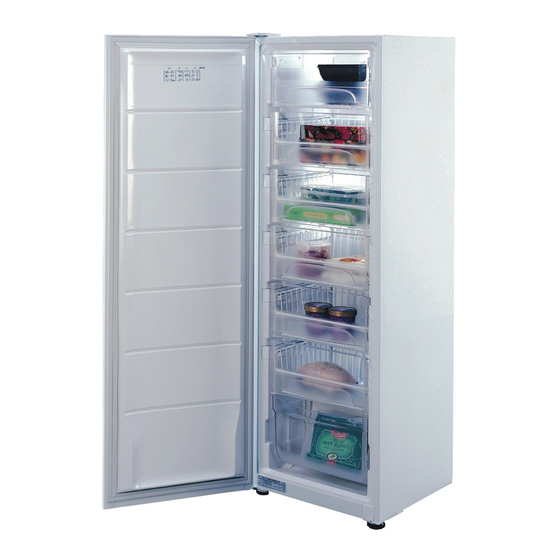
Fisher & Paykel E210 Service Manual
Electronic vertical freezers
Hide thumbs
Also See for E210:
- Installation instructions and user manual (44 pages) ,
- Manual (7 pages) ,
- Installation instructions and user manual (36 pages)
Table of Contents
Advertisement
Advertisement
Table of Contents

Summary of Contents for Fisher & Paykel E210
- Page 1 ELECTRONIC VERTICAL FREEZERS Models E150, E210, E308, E388 517798...
- Page 2 517798...
- Page 3 517798 APRIL 2006 REPRINT JULY 2006 The specifications and servicing procedures outlined in this manual are subject to change without notice. The latest version is indicated by the reprint date and replaces any earlier editions. Fisher & Paykel Appliances Ltd Fisher &...
-
Page 4: Table Of Contents
517798 CONTENTS INTRODUCTION ........................5 Electronics........................5 Product Specification....................5 1.2.1 Compressors/Refrigerant Charge................5 1.2.2 Compressor Specification..................5 Condenser Layout ......................6 Suction Line Assembly ....................6 Bottom Step Evaporator .....................6 ELECTRONICS ........................6 Control Module ......................6 Temperature Controller ....................6 Temperature Sensors....................6 Beeper/Alarm ......................7 Defrost Heater ......................7 FC Fan ........................ -
Page 5: Introduction
Showa fin on tube type evaporator. The internal condenser and cabinet do not change. Product Specification 1.2.1 Compressors/Refrigerant Charge Product Model Compressor Part Number Refrigerant Charge E150 207119 85 grams R134a E210 207120 105 grams R134a E308 207120 105 grams R134a E388 207121 115 grams R134a VF-300EX... -
Page 6: Condenser Layout
517798 Condenser Layout The compressors have no oil cooler lines; therefore the re-routing of the condenser is as follows: Discharge line from the compressor runs directly to the condenser on the back panel. From the back panel it enters the base panel, then through the left-hand side condenser, into the right-hand side condenser, then to the filter dryer capillary. -
Page 7: Beeper/Alarm
517798 Thermistor Sensors Resistance Table Temperature (ºC) Resistance (K Ω ± 5%) -30.0 25.17 -25.0 19.43 -20.0 15.13 -15.0 11.88 -10.0 9.392 -5.0 7.481 6.000 4.844 10.0 3.935 15.0 3.217 20.0 2.644 25.0 2.186 30.0 1.817 35.0 1.518 40.0 1.274 45.0 1.075 50.0... -
Page 8: Defrost Cycle
517798 Defrost Cycle The defrost heater is controlled by the control module, which switches it via a relay. The defrost interval can vary from between 12 hours to 22 hours of compressor run time, depending on the duration time of the last defrost. When the control module switches the compressor off for the defrost, there is a 2 minute delay (warm up time) before the defrost element is turned on. - Page 9 517798 Fault 3: 3 beeps Reason: The resistance of FC sensor is outside the normal range (> 45K Ohms) Primary Action: Check the 4-way connector at the control module. Secondary Action: Check sensor resistance. Reterminate the 4-way connector. Tertiary Action: Replace control module.
-
Page 10: To Disable Alarm
517798 To Disable Alarm Turn the control knob fully clockwise and then fully anticlockwise within 5 seconds. To Manually Force a Defrost Open the door for 5 seconds, then shut the door, turn the control knob fully clockwise and then fully anticlockwise within 10 seconds. -
Page 11: To Replace Defrost Sensor
517798 4.3.2 To Replace Defrost Sensor Unplug the refrigerator from the outlet socket. Remove evaporator cover. Remove the affect sensor from its holder. Cut the sensor from the loom and replace it by soldering and heat shrinking the new sensor to the loom. Replace sensor into its holder. -
Page 13: Wiring Diagram
517798 WIRING DIAGRAM... - Page 14 517798...
-
Page 15: Fault Finding
517798 FAULT FINDING The following faults and probable causes have been listed with the assumption that all basic checks have been carried out, such as product has power, door is closing correctly etc. Compressor Won’t Start. Check continuity of overload. If no continuity, replace overload. Check start and run winding (as per specification).


Need help?
Do you have a question about the E210 and is the answer not in the manual?
Questions and answers
Is a defrost heater still available as a spare part
Yes, the Fisher & Paykel Defrost Heater Model E210 is available as a spare part for $165.00.
This answer is automatically generated