Table of Contents
Advertisement
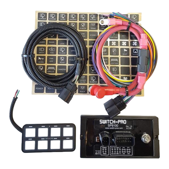
SP9100 8-Switch Programmable Switch Panel Power System
1. You MUST connect the Lt. Blue Ignition sense wire to an ignition or accessory source for the switches to operate.
The default setting for all switches is "Ignition" controlled.
2. Connect the black ground wire directly to the Negative terminal of the battery. DO NOT connect to frame ground
studs or ground distribution studs.
3. Do not connect any other power feeds to the power module's power stud.
4. Do not use the SP9100 to control a winch. Use the winch manufacturer's supplied device
5. Do not modify the switch panel communications cable.
6. Recommended installation of Power Module is the VERTICAL position, so that water runs off and does not
collect on the top of the connector, or face of the module. Failure to do so will compromise the integrity of the
water proof rating (IP67), and affect warranty coverage.
7. The use of a Terminal Block IS NOT RECOMMENDED, as wires are left exposed and susceptible to water and
corrosion.
The SP9100 Switch Panel Power system is a solid state switching system that is fully programmable and features Apple
and Android Bluetooth accessibility and RGB backlighting.
The switch panel has 8 switches and one programming switch. A red led indicates when the switch panel is in
programming mode and a blue led indicates when a Bluetooth connection is present.
The power module has 8 outputs, switches 1 – 4 are rated at 20A, and switches 5 – 8 are rated at 35A.
The power module also has 3 inputs, one Ignition sense, one Lights sense that can also be configured as an external trigger
input Trigger 2, and one dedicated external trigger input Trigger 1.
The Trigger 1 and Trigger 2 inputs can be configured to sense active high or active low inputs. Both trigger inputs can
switch on up to 4 outputs. The power module has 3 led indicators to display the status of each input.
The switch panel has an idle mode and a sleep mode. The idle mode will start after 1 minute of inactivity with a current
draw of 5.5mA. The sleep mode will start after 8 hours (default) of inactivity which is adjustable in the App with a current
draw of 3.0mA. If switch panel backlighting is on, the system WILL NOT enter sleep or idle mode.
The idle mode will activate when all switches are off, no Bluetooth connection, no Ignition, light, or trigger inputs.
In idle mode, the system will still respond to all inputs including switches and Bluetooth.
The sleep mode will activate when all switches are off, no Bluetooth connection, no Ignition, light, or trigger inputs.
In sleep mode Bluetooth is disabled, but all other inputs (except lights input), including switches will wake up the system.
.
Pg
1
Read this before installing!
Overview
1/2018
Advertisement
Table of Contents

Related Manuals for Switch-Pros SP9100

Summary of Contents for Switch-Pros SP9100
- Page 1 Overview The SP9100 Switch Panel Power system is a solid state switching system that is fully programmable and features Apple and Android Bluetooth accessibility and RGB backlighting. The switch panel has 8 switches and one programming switch. A red led indicates when the switch panel is in programming mode and a blue led indicates when a Bluetooth connection is present.
- Page 2 Installation Disconnect the negative battery lead from the vehicle’s battery before proceeding with installation, and to avoid damage to the electrical system! See the last page for vehicle specific installations. 1. Installing the Switch Panel Identify which accessories you will be powering with your Switch Panel Power System. Remember that Switches 1-4 are limited to 20 amps, and switches 5-8 are limited to 35 amps.
- Page 3 Switch panel harness connector removal When installing the switch panel communications harness it might be necessary to remove the black MOLEX 4-pin connector in order feed the harness through tight spaces. Follow the procedure below to remove the terminals. Check the 4-pin Harness Connector pin-out drawing above for proper wiring.
- Page 4 30 A. In this case it would be wise to set the over current limit to 35 A (using App). Connect the accessory directly to the output wires of the power module. The SP9100 switches 12V to the accessory.
- Page 5 The control wire connections can be connected using the supplied Fuse-Tap or Tapa-Circuits: When using the Fuse-Tap, it will come with a pre-installed fuse for the tap. Remove the fuse from the fuse box that needs to be tapped into, and insert it into the empty slot of the Fuse-Tap. Then insert the Fuse-Tap into the fuse slot.
- Page 6 1/2018...
- Page 7 SP9100 Functions scroll down to the left bottom of the screen and press the “Settings” button. In the App, The following programming bars will appear, tap the bar to enter the desired programming function. 1. Config Switches ON/OFF or Momentary*, default is On/OFF ...
- Page 8 The name of the Bluetooth radio can be changed, limited to 8 characters. This is the device name of the SP9100 switch panel that will appear after pressing “scan for devices”. It can be changed in the App settings menu under “Radio Name”. The default name is “SWCHPRO.” This is useful when there are multiple panels within Bluetooth range.
- Page 9 4. Scroll down to the left bottom of the screen and press the “Settings” button. From there you will see the different programming options, see the SP9100 functions page for details. 5. In the Settings menu you will be able to set a password for the Bluetooth connection, under the “Set Password”...
- Page 10 Special Switch Functions Control Bluetooth connection, Sleep mode, and External Trigger functions can be controlled through the switch panel by pressing and holding the programming switch and then pressing and releasing the desired function switch. Bluetooth Control: Bluetooth control can be disabled by pressing and holding the programming switch and pressing switch 1.
- Page 11 Programming your SP9100 through the switch panel Basic switch functions like ON/OFF-Momentary, Ignition-Battery, Flash, Strobe, Low Voltage Disconnect, and the Memory function can be programmed directly through the panel and do not require a Bluetooth connection. Switch panel backlighting and switch indicator led brightness can also be programmed directly through the switch panel.
- Page 12 Specifications Power Module: Switch Panel: Size: Width 3.0”, Length 6.0”, Height 0.5”, Size: Width 2.0”, Length 4.0”, Height 0.375” Height with connectors 1.40”, Housing material: Anodized Aluminum Height with connectors plugged in and wires 3.0” Switch Membrane and Legends material: Polycarbonate Material: Anodized Aluminum Temperature rating: -30C to 85C Temperature rating: Automotive -40C to 125C...
- Page 13 Vehicle Specific Installations: Jeep JK 2007 to 2017 Power module mounting: Mount the power module on the passenger side firewall above the battery. Secure the Power Module to mounting plate, using 2 M4 screws and 2 M4 nuts with locking washer. Nuts must be placed on the front of the PM, due to limited clearance on the back side.
- Page 14 Polaris RZR 1. Install the power module near the battery and connect the 4 AGW battery cable directly to the positive terminal of the battery. The battery connection can also be switched with a main cut-off switch. Connect the BLACK negative ground wire coming out of the 16-pin connector, directly to the negative terminal of the battery.
Need help?
Do you have a question about the SP9100 and is the answer not in the manual?
Questions and answers