Advertisement
Quick Links
Advertisement

Subscribe to Our Youtube Channel
Related Manuals for Peavey Unity DR16


Summary of Contents for Peavey Unity DR16
- Page 1 Unity DR16 ™ Digital Mixing Console Quick Start Guide www.peavey.com...
- Page 2 FCC/ICES Compliancy Statement This device complies with Part 15 of the FCC rules and Industry Canada license‐exempt RSS Standard(s). Operation is subject to the following two conditions: (1) this device may not cause harmful interference, and (2) this device must accept any interference received, that may cause undesired operation. Le présent appareil est conforme aux CNR d’lndustrie Canada applicables aux appareils radio exempts de licence. L’exploitation est autorisée aux deux conditions suivantes: (1) I’appareil ne doit pas produire de brouillage, et (2) I’utilisateur de I’appareil doit accepter tout brouillage radioélectrique subi, même si le brouillage est susceptible d’en compromettre le fonctionnement. Warning: Changes or modifications to the equipment not approved by Peavey Electronics Corp. can void the user’s authority to use the equipment. Note – This equipment has been tested and found to comply with the limits for a Class B digital device, pursuant to Part 15 of the FCC Rules. These limits are designed to provide reasonable protection against harmful interference in a residential installation. This equipment generates, uses, and can radiate radio frequency energy and, if not installed and used in accordance with the instructions, may cause harmful interference to radio communications. However, there is no guarantee that interference will not occur in a particular installation. If this equipment does cause harmful interference to radio or television reception, which can be determined by turning the equipment off and on, the user is encouraged to try and correct the interference by one or more of the following measures. Reorient or relocate the receiving antenna. Increase the separation between the equipment and receiver. Connect the equipment into an outlet on a circuit different from that to which the receiver is ...
- Page 3 The UNITY Series grows with your pro audio needs. Control the mixer from any iOS/ Android/Win/Mac device, whether you are running front of house or your own monitor mix. The UNITY DR16 also allows you to record audio of the stereo mix to a connected USB drive.
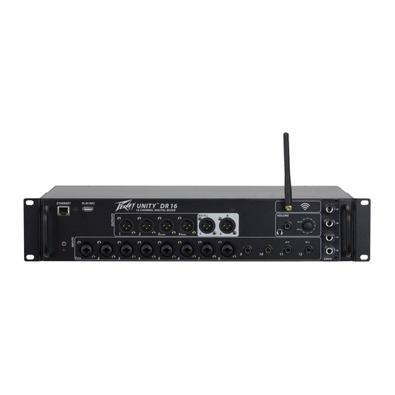
- Page 4 Front Panel Ethernet Connection (1) For connecting the Ethernet. Play/Rec USB Media Port (2) WiFi Antenna (3) Power LED (4) LED illuminates when power is supplied to the unit. XLR Outputs (5) Ground compensated balanced XLR output. XLR/TRS Inputs (6) This combination input jack accepts a ¼”...
-
Page 5: Iec Power Connector
Rear Panel IEC POWER CONNECTOR (10) This is a standard IEC cable connector for use with standard voltages from AC wall outlets. Its safety ground pin is connected to the chassis and should never be removed (or defeated in the line cord) for any reason. The IEC connector contains an internal fuse holder. - Page 6 Software Overview EDIT: Allows selection of the editing view (i.e. the mixer overview in the picture above) USB Recording/Playback, “RTA” , “Save”/“- Load” the current configuration to/from PC and “Set default configuration”. (Reset) (1) EDIT Process: the content of this section changes depending on which edit button is selected (i.e. when the button “MIXER” is selected it shows an overview of the current settings of the input channels, the bus send gains, the active input processes, etc.) (2) MONITOR: This section displays the information for the headphone, control-room wedge monitor system..
- Page 7 (1) Select Mixer Overview Sect. (2) Select Inputs Edit Sect. (3) Select Effects Edit Sect. (4) Select Ducker Edit Sect. (5) Select Feedback Eliminator Sect. (6) Select Main Edit Sect. (7) Select Aux 1/2/3/4 Edit Sect. (8) Select Output Aux Level Sect. (9) Select Setup Sect.
-
Page 8: Mixer Overview
EDIT Process Section MIXER OVERVIEW After selected the “MIXER” button, the edit process section is updated to display the following: Here, the user can see the status of the Input Channel parameter settings and the sends levels to the Aux and Effects Buses. - Page 9 INPUT Section After selecting the “INPUT” button, the Edit Process Section is updated to display the following: 1. Led Clip Indicator 2. Vu-Meter before processing 3. LED Signal presence indicator 4. Led Clip Indicator 5. Activity of the Compressor (yellow line) 6.
- Page 10 –SOURCE: for CH1 to CH8 the user can select between LINE and MIC for CH9 to CH12 the source is fixed to LINE for CH13 to CH16 the user can select either LINE and USB if the ANALOG-EXTENSION CARD is installed, or either DANTE and USB if the DANTE-EXTENSION CARD is installed.
- Page 11 –MID-Morph: when disabled (button colored grey, OFF) the 4 EQ filters work as a standard EQ,when enabled (button orange color, ON) then the EQ engages Peavey’s proprietary Mid-Morph where where the Frequency,- Type and Q are fixed with the user controlling the gain.
- Page 12 EFX Section After selecting the “EFX” button, The Edit Process section is updated to display the following: Here the User can edit all effect parameters. To edit the value use the same procedure used on the Input Gain. There are 4 available effects: EFX1: REVERB •Density: from 0% to 100% •Decay: from 0.5sec to 8sec step 0.05sec...
- Page 13 After selecting the value of the note, select the desired BPM and the value of the delay will be calculated, if the value calculated is different from the current delay value then the button with the value of the delay will blink, the user must click on the button in order to send the new value to the device.
- Page 14 the same parameter using on Chorus and Tremolo •FLANGER+TREMOLO the same parameter using on Flanger and Tremolo •PHASER+TREMOLO the same parameter using on Phaser and Tremolo There are also the following parameters common for each effect type: •HP/LP Filter: Bypass, 1st and 2nd order Butterworth Filter; frequency from 20Hz to 20kHz step1Hz •EQ Filter: the single filter can be enabled or disabled using the ON/OFF Button.The filter type is Peak (BELL), the frequency can be set to a range of 20Hz-20kHz step 1Hz, the Gain of the filter can be change to a range of +/-12dB and the Q factor of the filter can changed from 0.3 to 20.
- Page 15 DUCKER Section After selecting the “DUCKER” button, the Edit Section will update the display the following: To use the Ducker the user must enable the DUCKER (color orange, ON) once active, the user must decide the priority channel (in the picture above the input CH.1 and CH.2 have priority and the remaining channels do not have priority).
- Page 16 Feedback Eliminator After selecting the “FBK ELIM” button, the Edit Section will update to display the following: There are two feedback eliminators available to the first 8 input channels. It is not possible to assign the two Feedback Eliminators to the same channel. The Feedback Eliminator is not active until the Enable button is set to ON.
- Page 17 MAIN Section After selecting the MAIN button, The Edit Process section is updated to display the following: As the Main Left/Right parameters are always linked, the interface only displays one channel. In the main sec- tion, the user can edit the following parameters: –POLARITY: Normal/Invert: When the button is ON (Orange color) the polarity of the Main output signals are inverted.
- Page 18 using the mouse directly via the EQ handles. Click and hold the left mouse button on the square colored handle (one color for one filter) and move the mouse up/down to change the gain and Left/Right to change the frequen- cy.
- Page 19 AUX 1/2/3/4 Section After selecting the “AUX1/2/3/4” button, the sw show the following frame: 1. LED Clip indicator 2. Vu-Meter before the process 3. LED Clip indicator 4. Compressor Activity (Yellow Line) 5. Vu-Meter after processing 6. Graph PEQ filter, Hp, Lp filter and GEQ In the AUX Section the user can edit the following parameters: –POLARITY: When the button is ON (Orange color) the polarity is set to 180°...
- Page 20 1. Graphic EQ section 2. Parametric EQ section, same filter used on the AUX frame 3. HP/LP section, same filter used on the AUX frame...
- Page 21 LEVEL Section After selecting the Level button, The Edit Process section is updated to display the following: 1. LED Clip Indicator 2. Compressor Activity (Yellow Line) 3. Vu-Meter after processing 4. Vu-Meter after fader output In this section, the user can adjust the Level of the Aux 1/2/3/4 Outputs (-inf to 12dB). The output of Aux 1/2/3/4 can also be muted.
- Page 22 Setup Section After selected the Setup button, The Edit Process section is updated to display the following: 1. Host Address IP 2. Device List info 3. Search all devices connected to the network In this section, the user can select the following views: -Connection -Access point setup (see appendix 2) -WLAN setup (see appendix 2)
-
Page 23: Firmware Update
ACCESS POINT, WLAN, LAN: please see appendix 2 FIRMWARE UPDATE: when new firmware is released, the user can download it from the Peavey website and update the device via re- mote control. After clicking on the “FW UPDATE” button, the software shows the following windows after selecting the IP address of the device to update, the following window appears: 1. - Page 24 Load the new firmware .sfu file and press the Update icon. When the update is finished, the sw shows the mes- sage “Firmware successfully loaded!”. NAME EDIT: After clicking on the “NAME EDIT” button, the sw shows the following window Here the user can change the label of the Input CH, AUX, DCA, EFX and device name.
- Page 25 RTA Button: After clicking on the “RTA” button then the sw shows the following window 1. Close window 2. Select RTA Source Channel Monitor Left Monitor Right Monitor L+R Main Left Main Right Main L+R AUX1 AUX2 AUX3 AUX4 3. Set number of samples: 2048 4096 8192...
- Page 26 -MONITOR: 1. Output Level Left and Right 2. Link Left and Right 3. Output Mute Left and Right 4. Select Monitor Source 5. Vu-Meter Left and Right 6. Send monitor L/R to the AUX3/4 Output or send monitor L+R to AUX4 Output.
- Page 27 Output L/R Main 1. Led Clip Left indicators: Right (after fader), Left (after output MAIN process) 2. Fader: Output Main left level 3. Left VuMeter: Left (after Fader), Right (after output MAIN process) 4. Mute/UnMute Left/Right output Main 5. Led Clip Right indicators: Right (after fader), Left (after output MAIN process) 6.
- Page 28 BUS SECTION: Bus Section allows mixing to each Mix Bus. Main Bus Sends To control the Main L/R bus mixing click the MAIN button in the BUS Section. 1. Source Info 2. Pan 3. Led Clip indicator (after input channel process) 4.
- Page 29 AUX1/2/3/4 BUS SENDS To control the AUX1-4 bus mix, click the AUX1-4 buttons in the BUS Menu. 1. PRE/PST selection for the Aux Bus Send 2. Channel Sends to the selected Bus 3. Selected Bus SOLO/SOLO GROUP 4. DCA ASSIGN FX1/2/3/4 BUS SENDS To control the EFX1-4 bus mixing click the EFX1-4 button in the BUS Menu.
-
Page 30: Dca Group
Mute/ Solo Group 1. Mute OFF/ON 2. Solo OFF/ON The remote device can manage up to 4 MUTE Groups and up to 4 SOLO Groups. When the User changes the status (OFF/ON) in the Mute group frame, the status of the Mute on all channel linked to this group will be OFF/ON. - Page 31 Appendix1 DR16 Mixer - How to connect via WiFi Module 1) Install the Unity Mixer PC APP on your PC. *Note* Setup will require the NET 4.0 Framework. 2) Turn on the DR16 Mixer and connect the “DR16” WiFi network on yourPC. 3) Run the Unity PC APP.
-
Page 32: Ethernet Connection
Appendix 2 Appendix 2 Ethernet Connection Ethernet Connection (LAN) The DR16 integrates a 100Mbit/s Ethernet port allowing a full real-time remote control and monitor of the mixer processing functions. The DR16 has an integrated a 100Mbit/s Ethernet port that allows for a full real-time remote control and moni- toring of the mixer processing functions. - Page 33 - Gateway: 192.168.0.1 Appendix 2 Ethernet Connection The DR16 integrates a 100Mbit/s Ethernet port allowing a full real-time remote control and monitor of the mixer processing functions. A remote controller (e.g. a laptop) can connect the DR12 in two different modes: 1) Point-To-Point mode 2) LAN mode 2) LAN mode...
-
Page 34: Wifi Connection
WiFi Connection WiFi Connection The Unity Mixer has an integrated WiFi module for full real-time remote control and monitoring of the mixer The DR12 integrates a WiFi module for a full real-time remote control and monitor of the mixer processing functions. processing functions. - Page 35 Unity Mixer WiFi module 2) WiFi Client (Station) mode 2) WiFi Client (Station) mode (WLAN) In WiFi Client mode the module connects to a WiFi network and supports DHCP client or static IP In WiFi Client mode the module connects to a WiFi network and supports DHCP client or static IP addressing. addressing.
- Page 36 - Key: xxxxxxxx. Password of the WiFi router network Connection Parameters (Remote Controller): Connection Parameters (Remote Controller): - IP Addressing: Dynamic (DHCP Client) Connection Parameters (Remote Device): - IP Addressing: Dynamic (DHCP Client) Note: IP Address, Net Mask and Gateway are automatically assigned by the DHCP server (i.e. the - IP Addressing: Dynamic (DHCP Client) WiFi router) Note: IP Address, Net Mask and Gateway are automatically assigned by the DHCP server (i.e.
- Page 37 Multiple System Control WiFi Control of multiple DR mixers in the same system or facility. When two or more DR mixers are operated in the same area, the WiFi settings in the mixers must be modified for proper operation. There are two different approaches that can be used for operation of multiple units. The first method works as long as the control devices (computer or mobile device) will be used to operate only one of the mixers.
- Page 38 Change the device name from DR16 to a name you can use to identify this particular mixer. Above, DR16 was changed to DR16 #1. (I am sure you can do better for your application) Now click apply. The mixer will need to be powered off then on for these changes to be applied. Repeat this process for the other mixers in the system giving each their own unique SSID and Name.
- Page 39 Once each of mixers have been connected, you click the status column to select the mixer you wish to control. You will notice that there are two listings for each of mixers. The LAN connection was used to configure the mixer using an Ethernet link and the WLAN connection uses the WiFi network.
- Page 40 USB RECORDING/PLAYBACK Clicking on the “USB” button brings up the USB Recording/Playback window, which allows you to record or play back stereo audio files from a connected USB thumb drive. The user can also create and store playlists of audio files. The DR 16 mixer records the stereo audio files in a 16 bit “.wav” format with a 48 kHz sample rate. 1.) RECORD BUTTON –...
-
Page 41: Specifications
Specifications DR16 Specifications Inputs(main output) Input levels Function Input Z Input Gain Bal/Unbal Connector (ohms) Setting Min** Nominal* Max* Microphone MAX G +46dB -71dBu -35dBu -24dBu XLR/TRS combo jacks (1-8CH) Gain +28dB -53dBu -17dBu -12dBu MIN G +10dB -35dBu +1dBu +8dBu Pin 1 Sleave (Gnd) Line... - Page 42 Min** Input Leve(sensitivity) is the smallest signal that will produce nominal ouput (+4 dBu)with channel and master faders set for maximum gain. Nominal* settings are defined as all controls set at 0 dB(or 50% rotation for rotary pots)except the gain adjustment pot which is as specified. Max* are defined as maximun input levels at the total harmonic distortion<0.05 Outputs Output Levels...
- Page 43 Output Residual Noise S/N Ratio(Ref:+4dBu) Test Conditions Master Left/Right -93dBu 97dB Master Fader Down, Channel Levels Down -93dBu 97dB Master Fader Nominal, Channel Levels Down -88dBu 92dB Master Fader Nominal, Channel Levels Nominal, Panned Odd Chanels(left) Even Channels(right) Monitor Send -81dBu 85dB All controls off...
- Page 44 Warranty registration and information for U.S. customers available online at www.peavey.com/warranty or use the QR tag below Features and speci cations subject to change without notice. Peavey Electronics Corporation 5022 Hartley Peavey Drive Meridian, MS 39305 (601) 483-5365 FAX (601) 486-1278 Logo referenced in Directive 2002/96/EC Annex IV (OJ(L)37/38,13.02.03 and defined in EN 50419: 2005...
Need help?
Do you have a question about the Unity DR16 and is the answer not in the manual?
Questions and answers