Table of Contents
Advertisement
Quick Links
Advertisement
Table of Contents
Troubleshooting

Related Manuals for Crafco SS60-Diesel

Summary of Contents for Crafco SS60-Diesel
- Page 1 Parts Manual - 26618 Revision B...
- Page 2 Fill in appropriate fields that apply to this machine Machine S/N: _ _______________________________ Hose S/N: _______________________________ Hose S/N: _______________________________ Pump S/N: _______________________________ Pump S/N: ______________________________ Engine S/N: ________________________________ Compressor S/N: _____________________________ Gear Box S/N (Patcher): ______________________ Blower S/N (Magnum): ________________________...
- Page 3 SUPER SHOT 60 Diesel Melter Part Manual Revisions Revision Date Updated to new format. 6/9/2015 Added trailer mount information 8/2016...
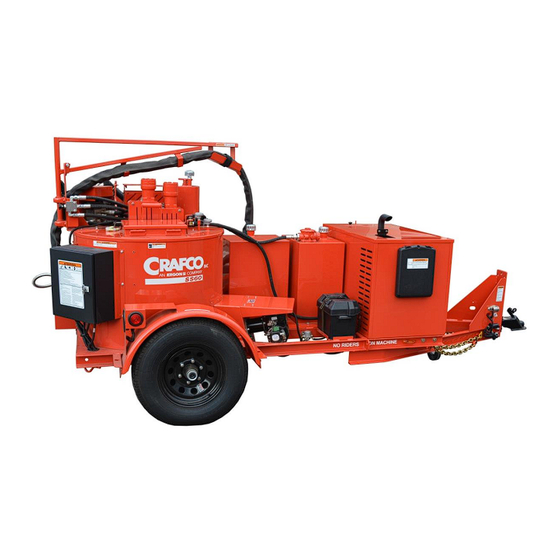
- Page 4 SUPER SHOT 60 DIESEL SKID MOUNT MELTER PN 46800 SUPER SHOT 60 DIESEL TRAILER MELTER PN 46950...
-
Page 6: Table Of Contents
Super Shot 60 Diesel Melter Part Manual Table of Contents 1.0 About This Manual ........................1-1 1.1 How to use this manual: ...................... 1-1 2.0 Safety Precautions ........................2-1 2.1 General Safety ........................2-1 2.2 Personal Safety ........................2-1 2.3 Equipment or Operational Safety ..................2-1 2.4 Safety Symbols and Notices .................... - Page 7 8.4.2 Pump Hydraulic Troubleshooting ................8-35 9.0 About the Illustrated Parts List....................9-1 9.1 Ordering Crafco Parts ......................9-1 9.2 Super Shot 60 Diesel Skid Mount Melter ................9-2 9.3 Super Shot 60 Diesel Trailer Melter ..................9-6 9.4 Tank Assembly ........................9-10 9.5 Control Box Assembly .......................
- Page 8 Super Shot 60 Diesel Melter Part Manual Table of Contents 10.0 Tools and Accessories ......................10-1...
- Page 9 Super Shot 60 Diesel Melter Part Manual List of Figures Figure 5.1 Hydraulic Fluid Level and Temp. Gauge ..............5-2 Figure 5.2 Heat Transfer Oil Dipstick .................... 5-2 Figure 6.1 Lug Bolt Tightening Sequence ..................6-1 Figure 6.2 Scale Plate ........................6-2 Figure 6.3 Material Pump Replacement ..................
- Page 10 Super Shot 60 Diesel Melter Part Manual List of Tables Table 2-1 Safety Symbols and Notices ..................2-2 Table 2-2 Safety Symbols and Notices (continued) ............... 2-3 Table 4-1 Machine Specifications ....................4-1 Table 5-1 Preparing the Machine for Start Up ................5-1 Table 5-2 Starting the Burner ......................
- Page 11 Super Shot 60 Diesel Melter Part Manual List of Tables Table 8-13 Sealant is Heating Slowly ..................8-11 Table 8-14 Basic Visual Mixer Troubleshooting................8-12 Table 8-15 Mixer Electrical Troubleshooting ................8-13 Table 8-16 Mixer Electrical Troubleshooting (continued) ............. 8-14 Table 8-17 Mixer Electrical Troubleshooting (continued) .............
- Page 12 Super Shot 60 Diesel Melter Part Manual List of Tables Table 9-13 Hydraulic Diagram: PN 46959 ................... 9-25 Table 9-14 Hydraulic Diagram: PN 46959 (continued) ..............9-26 Table 9-15 Electrical Schematic ....................9-29...
-
Page 13: About This Manual
Chapter 1 Introduction 1.0 About This Manual This manual is supplied with each new Crafco Super Shot 60 Diesel Melter. The manual assists your machine operators in the proper use of the melter applicator and provides information about the machine’s mechanical functions. -
Page 15: Safety Precautions
Or contact your nearest authorized Crafco Distributor at crafco.com/Distributors. 2.1 General Safety Crafco, Inc. assumes no liability for an accident or injury incurred through improper use of the machine. Read this manual thoroughly before operating the machine. -
Page 16: Safety Symbols And Notices
Protective Gloves Wear heat resistant gloves. Protective Face or Eye Wear Wear face shield or safety glasses. Do not stand between trailer and hitch when hooking Body Crush Hazard melter to truck. ©2016 by Crafco, Inc. All Rights Reserved………………………………………..…………………………………Safety 2-2... -
Page 17: Table 2-2 Safety Symbols And Notices (Continued)
Crush Hazard Keep feet and legs clear. Pinch Hazard Keep hands and feet clear. Exhaust Hazard Avoid breathing engine exhaust. Read and understand operator and safety manuals Read Manual before operating machine. ©2016 by Crafco, Inc. All Rights Reserved………………………………………..…………………………………Safety 2-3... -
Page 19: Limited Warranty
CAUTION Use of replacement parts other than genuine Crafco parts may impair the safety or reliability of your equipment and nullifies any warranty. ©2016 by Crafco, Inc. All Rights Reserved………………………………………………………….…Warranty Information 3-1... -
Page 20: Warranty Claim Instructions
RA number. The customer will be emailed or faxed an RA form with all instructions to return the item to Crafco, Inc. See example. If the part is found to be within the one year warranty period and has not been abused or modified, a credit will be issued to the customer’s account or credit card. - Page 21 CAUTION Use of replacement parts other than genuine Crafco parts may impair the safety or reliability of your equipment and nullifies any warranty. ©2018 by Crafco, Inc. All Rights Reserved………………………………………………………Warranty Information 3-1...
- Page 22 RA number. The customer will be emailed or faxed an RA form with all instructions to return the item to Crafco, Inc. See example. If the part is found to be within the two year warranty period and has not been abused or modified, a credit will be issued to the customer’s account or credit card.
-
Page 23: Machine Specifications
3,200 Lbs. (1,451 kg) Diesel tank Capacity 26 Gallons (98.4 Liters) Hydraulic Tank Capacity 26 Gallons (98.4 Liters) Single Torsional Axle Capacity 4,200 lbs. (1,905 kg) ST225/75 R15 Tires (Load Range D) ©2016 by Crafco, Inc. All Rights Reserved……………………………………………………………Machine Specifications 4-1... -
Page 25: Operating Instructions
Super Shot 60 Diesel Melter Part Manual Chapter 5 Operating Instructions 5.0 Operating Instructions The Crafco Super Shot 60 Diesel was developed to melt Crafco sealants. However, it works well with most road asphalt and federal specification crack or joint sealants. Note: DO NOT attempt to operate the machine without using these and all other instructions. -
Page 26: Figure 5.1 Hydraulic Fluid Level And Temp. Gauge
Super Shot 60 Diesel Melter Part Manual Chapter 5 Operating Instructions Figure 5.1 Hydraulic Fluid Level and Temp. Gauge Dipstick for Heat Transfer Oil Figure 5.2 Heat Transfer Oil Dipstick ©2016 by Crafco, Inc. All Rights Reserved………………..…………………………………..….Operating Instructions 5-2... -
Page 27: Machine Start Up For Electric Hose
(135°C). The red light marked ‘HEATED HOSE” will illuminate when the hose control is calling for heat. Adjust the temperature dial to the manufacturer’s recommended temperature. Note: The hose reaches operating temperature in approximately 30 minutes. ©2016 by Crafco, Inc. All Rights Reserved………………..…………………………………..….Operating Instructions 5-3... - Page 28 DO NOT remove the hose from the boom during operation or kinking will occur. Important: It is strongly recommended that the hose be stored in the boom (locked position) when not in use or when in transit. This will prevent twisting or kinking. ©2016 by Crafco, Inc. All Rights Reserved………………..…………………………………..….Operating Instructions 5-4...
-
Page 29: About The Heated Hose, Wand, Valve, And Tip Guard
INSTALL 26084 MINI GEAR CLAMP ONTO THE DUCKBILL VALVE 50270 26083 CLAMP NEEDS TO BE ROTATED TO THE SIDE AS SHOWN. THIS KEEPS IT FROM CATCHING ON SHOEBOX. DETAIL A 50278 ©2016 by Crafco, Inc. All Rights Reserved………………..…………………………………..….Operating Instructions 5-5... -
Page 30: Electric Hose Care And Cautions
Note: Do not twist or bend the hose over sharp edges such as the edge of the frame or tank. Crafco, Inc. recommends you do not work directly under the boom; this may cause damage to the hose. Follow all machine instructions in this manual. -
Page 31: Loading Material Into The Sealant Tank
When sealant placement volume is low, or the crew has stopped working for lunch hot oil and material temperatures can equalize. To lower material temperature add a few blocks of cold sealant. This may not be an option if the tank is full. ©2016 by Crafco, Inc. All Rights Reserved………………..…………………………………..….Operating Instructions 5-7... -
Page 32: Material Tank Depth Chart
42.84 162.17 15.88 60.11 385.6 45.90 173.75 12.82 48.53 48.96 185.33 9.76 36.95 436.4 52.02 196.92 25.36 461.8 55.08 208.50 3.64 13.78 487.2 58.14 220.08 0.58 2.20 487.43 58.72 222.28 0.00 ©2016 by Crafco, Inc. All Rights Reserved………………..…………………………………..….Operating Instructions 5-8... -
Page 33: Dispensing The Material
Adjust the pump speed for the desired flow rate for the application. The rate of flow may be varied while the pump is running. ©2016 by Crafco, Inc. All Rights Reserved………………..…………………………………..….Operating Instructions 5-9... -
Page 34: Shutting Down And Cleaning Out The Machine
5.8 Shutting Down and Cleaning Out the Machine When shutting down the machine for the day, Crafco recommends leaving the melter about half full with material. This will give a fairly rapid heat up rate in the morning, but allows enough material to start dispensing right away when the material becomes molten. -
Page 35: Maintenance Instructions
Second stage 50-60 foot pound (ft-lb) Third stage 90-120 foot pound (ft-lb) Tighten bolts and nuts in the sequence shown in Figure 6.1 Lug Bolt Tightening Sequence. 4-BOLT 5-BOLT 6-BOLT Figure 6.1 Lug Bolt Tightening Sequence ©2016 by Crafco, Inc. All Rights Reserved………………..…………………………………..….…Maintenance Instructions 6-1... -
Page 36: Figure 6.2 Scale Plate
(See Figure 6.2 Scale Plate) Knob Calibration Mark Figure 6.2 Scale Plate ©2016 by Crafco, Inc. All Rights Reserved………………..…………………………………..….…Maintenance Instructions 6-2... -
Page 37: Heat Transfer Oil
Once a year or as needed the material tank Scrape out built up material Material Sensor Guard around guard For a list of parts required for maintenance see Table 6-3 General Maintenance Parts. ©2016 by Crafco, Inc. All Rights Reserved………………..…………………………………..….…Maintenance Instructions 6-3... -
Page 38: Service Instructions
Refer to the material manufacturer’s instructions for recommendations. Note: Follow the recommended maintenance per Table 6-1 Maintenance Chart For service, find a list of authorized Distributors and service centers at Crafco.com/Distributors. 6.12 General Maintenance Parts Table 6-3 General Maintenance Parts Quantity Description Part No. -
Page 39: Recommended Spare Parts
Refer to engine manual 3 Qts. (2.8 L.) Hydraulic Oil Shell AW Hydraulic 46 26 Gals. (98.4 L.) Heat Transfer Oil Shell Turbo T 68 (Group II) 21 Gals. (82 L.) ©2016 by Crafco, Inc. All Rights Reserved………………..…………………………………..….…Maintenance Instructions 6-5... -
Page 40: Applicable Brands Of Heat Transfer Oil
Shell Turbo T 68 (Group II) CAUTION The heat transfer oil in this machine is a grade that has been tested and recommended by Crafco, Inc. Using a grade of oil not specifically recommended by Crafco, Inc., is cause for warranties to be voided. -
Page 41: Material Pump Replacement
Note: This will support the assembly while removing the pump from the tank. Remove the six (6) bolts attaching the pump to the tank. Lift the pump from the sealant tank. ©2016 by Crafco, Inc. All Rights Reserved………………..…………………………………..….…Maintenance Instructions 6-7... -
Page 42: Table 6-8 Material Pump Replacement (Continued)
Clean any sealant from the top of the pump mounting plate and clean the shaft holes. (See Figure 6.3 Material Pump Replacement) CAUTION Premature pump wear results if the pump mounting plate and bolt holes are not properly cleaned. ©2016 by Crafco, Inc. All Rights Reserved………………..…………………………………..….…Maintenance Instructions 6-8... -
Page 43: Figure 6.3 Material Pump Replacement
Super Shot 60 Diesel Melter Part Manual Chapter 6 Maintenance Instructions PUMP ASSEMBLY BOLTS PUMP MOUNTING BOLTS PUMP ASSEMBLY PUMP MOUNTING PLATE TANK BOTTOM Figure 6.3 Material Pump Replacement ©2016 by Crafco, Inc. All Rights Reserved………………..…………………………………..….…Maintenance Instructions 6-9... -
Page 45: How To Use A Multimeter
Touch one probe to each screw or wire of the sensor. The meter will read X.XX if in the 2K range or XXX.X if in the 2000 range. ©2016 by Crafco, Inc. All Rights Reserved………………..…………………………………..….…How to Use a Multimeter 7-1... -
Page 46: Checking Amperage
DC Voltage • Everything except Generator Use these ports. Do not AC Voltage ~ use the fuse port, it is for • Generator Output amps Figure 7.1 Standard Multimeter ©2016 by Crafco, Inc. All Rights Reserved………………..…………………………………..….…How to Use a Multimeter 7-2... -
Page 47: Figure 7.2 Clamp - On Amp Meter/Multimeter
• Hyd. Coils • Burner Ignition Coil AC Amps ~ • Hose Current Audible Continuity Hose, Wand, and wire connection Figure 7.2 Clamp – On Amp Meter/Multimeter ©2016 by Crafco, Inc. All Rights Reserved………………..…………………………………..….…How to Use a Multimeter 7-3... -
Page 49: Burner Troubleshooting
No go to Step 7. Yes, fill with #2 diesel fuel. Then bleed the Is the fuel level low or empty? burner, see Table 8-12 Bleeding the Burner. No, go to Step 8. ©2016 by Crafco, Inc. All Rights Reserved………………...………………………………..……………...Troubleshooting 8-1... -
Page 50: Table 8-2 Basic Visual Burner Troubleshooting (Continued)
Is your burner working properly, but it Table 8-13 Sealant is Heating seems to take a while to reach operating Slowly. temperature? No, Call Crafco, Inc. and speak to a customer service technician. Note: Figure 8.1 Diesel Burner Schematic while troubleshooting the burner electrical system. -
Page 51: Table 8-4 Burner Electrical Troubleshooting (Continued)
Is there 12Vdc between terminal #4 gray wire and terminal #8 black wire of the material between terminal block and terminal #4 of PAKSTAT? the material PAKSTAT. No, go to Step 7a. ©2016 by Crafco, Inc. All Rights Reserved………………...………………………………..……………...Troubleshooting 8-3... -
Page 52: Table 8-5 Burner Electrical Troubleshooting (Continued)
Is there 12Vdc between top terminal of circuit between top terminal of circuit breaker and breaker (red wire) and nearby ground source bottom terminal (red wire) of power switch. (black wire)? No, go to Step 12a. ©2016 by Crafco, Inc. All Rights Reserved………………...………………………………..……………...Troubleshooting 8-4... -
Page 53: Table 8-6 Burner Electrical Troubleshooting (Continued)
No, go to Step 14a. Yes, there should be 12Vdc at all previous Check connections and condition of red steps. battery cable No, replace battery cable. ©2016 by Crafco, Inc. All Rights Reserved………………...………………………………..……………...Troubleshooting 8-5... -
Page 54: Figure 8.1 Diesel Burner Schematic
12 GA. RED Pressure Switch 12 GA. RED 14 GA. RED 14 GA. RED WHT/GRN W HT/GRN Circuit Breaker Burner Solenoid BLACK BLACK Burner Plug Battery 12vdc Figure 8.1 Diesel Burner Schematic ©2016 by Crafco, Inc. All Rights Reserved………………...………………………………..……………...Troubleshooting 8-6... -
Page 55: Table 8-7 Smoke Coming Out Of Exhaust Stack
If it has been longer than 500 hours since the last time the burner nozzle was replaced, Crafco recommends replacing the burner nozzle at this time. Reassemble the burner, using the reverse order in Step 3. -
Page 56: Table 8-9 Testing The Dc Controller
Check the ohms between the terminals of fuel solenoid. If the reading is between 15-25 ohms the coil is good. If the reading is outside the above range or the meter indicates an open circuit, replace the fuel solenoid. ©2016 by Crafco, Inc. All Rights Reserved………………...………………………………..……………...Troubleshooting 8-8... -
Page 57: Table 8-11 Burner Ignition Coil Testing
Fuel should flow out of the bleeder valve. You want the fuel to be clear from any air bubbles, this may require you to turn the ignition key "OFF" and "ON" a couple of times. Allow burner to cycle itself off 30 seconds. Tighten the bleeder valve. ©2016 by Crafco, Inc. All Rights Reserved………………...………………………………..……………...Troubleshooting 8-9... -
Page 58: Figure 8.2 Diesel Burner Electrode Adjustment
AIR SETTING # FUEL PRESSURE ADJUSTMENT SCREW COPPER FUEL LINE NUT BLEEDER AIR BAND SCREW AIR SHUTTER AIR BAND FUEL PRESSURE GAUGE KIT FUEL PRESSURE GAUGE Figure 8.3 Diesel Burner Air Settings ©2016 by Crafco, Inc. All Rights Reserved………………...………………………………..……………...Troubleshooting 8-10... -
Page 59: Sealant Heating Slowly
Check your records of the last service replacement of the heat transfer oil. If it has been longer than 500 hours, or one year, you need to change your oil. Many of Crafco, Inc. service centers can perform these service steps for you if you cannot. Call your local service center to find out if they can. -
Page 60: Mixer Troubleshooting
Is the hydraulic fluid level near the center of Troubleshooting. the sight gauge? Check at ambient No, fill oil to the center of the sight gauge. temperature. See Figure 5.1 Hydraulic Fluid Level and Temp. Gauge. ©2016 by Crafco, Inc. All Rights Reserved………………...………………………………..……………...Troubleshooting 8-12... -
Page 61: Table 8-15 Mixer Electrical Troubleshooting
(black terminal block. wire). No on Red Lid and Yes on Pink-2, ensure yellow jumper bar is securely installed between the two terminal blocks. No, go to Step 4a. ©2016 by Crafco, Inc. All Rights Reserved………………...………………………………..……………...Troubleshooting 8-13... -
Page 62: Table 8-16 Mixer Electrical Troubleshooting (Continued)
No, go to Step 8a. Yes, replace circuit breaker. Is there 12Vdc between the bottom terminal of circuit breaker red wire labeled RED-2 and No, go to Step 9. nearby ground source (black wire)? ©2016 by Crafco, Inc. All Rights Reserved………………...………………………………..……………...Troubleshooting 8-14... -
Page 63: Table 8-17 Mixer Electrical Troubleshooting (Continued)
No, go to Step 10a. Yes, there should be 12Vdc at all previous Check connections and condition of red steps. battery cable? No, replace battery cable. ©2016 by Crafco, Inc. All Rights Reserved………………...………………………………..……………...Troubleshooting 8-15... -
Page 64: Figure 8.4 Checking Din Plug Voltage
Super Shot 60 Diesel Melter Part Manual Chapter 8 Troubleshooting Figure 8.4 Checking Din Plug Voltage ©2016 by Crafco, Inc. All Rights Reserved………………...………………………………..……………...Troubleshooting 8-16... -
Page 65: Figure 8.5 Mixer Circuit Schematic
Mixer Rev Coil with Light Coil AMP Draw 12vdc @2.71 AMPS Mixer Fwd Coil with Light Mixer Pump Rev Toggle Switch Toggle Switch Pump Rev Coil with Light Figure 8.5 Mixer Circuit Schematic ©2016 by Crafco, Inc. All Rights Reserved………………...………………………………..……………...Troubleshooting 8-17... -
Page 66: Mixer Hydraulic Troubleshooting
Next turn "OFF" the diesel engine, remove the cap and pressure gauge, then re-attach the hose. Yes, call Crafco, Inc. and speak to a Is the hydraulic flow 5.68 Liters/min (1.5 GPM) from the hydraulic valve? If you do not have... -
Page 67: Figure 8.6 Hydraulic Valve Pressure Setting
SET @ 1000 PSI ALLEN SCREW PRESSURE RELIEF JAM NUT Agitation Direction = Counterclockwise Material Pump = Clockwise Hydraulic Flow = 9.71 GPM (36.8 LPM) @ 2,550 RPM Figure 8.6 Hydraulic Valve Pressure Setting ©2016 by Crafco, Inc. All Rights Reserved………………...………………………………..……………...Troubleshooting 8-19... -
Page 68: Figure 8.7 Din Plug Layout
Chapter 8 Troubleshooting DIN PLUG #4 DIN PLUG #3 MIXER FORWARD MIXER REVERSE DIN PLUG #1 DIN PLUG #2 MATERIAL PUMP MATERIAL PUMP REVERSE FORWARD MOUNTING BRACKET Figure 8.7 Din Plug Layout ©2016 by Crafco, Inc. All Rights Reserved………………...………………………………..……………...Troubleshooting 8-20... -
Page 69: Hose Troubleshooting
30 Amps cold or 20-22 No, go to Step 3. Amps hot. NOTE: Always use a clamp-on amp meter to perform this test. Each wire should have the same amp reading (+/- 1 amp). ©2016 by Crafco, Inc. All Rights Reserved………………...………………………………..……………...Troubleshooting 8-21... -
Page 70: Table 8-21 Hose Electrical Troubleshooting (Continued)
#1. nearby ground source (black wire)? No go to Step 7a. Yes, call Crafco, Inc. and speak to a Is there 12Vdc between pink wire labeled “PNK-3 and nearby ground source (black customer service technician you should have wire)? been able to find the problem. -
Page 71: Figure 8.8 Junction Box Voltage Test
Super Shot 60 Diesel Melter Part Manual Chapter 8 Troubleshooting Test #2 between black and green wires Test #1 between black and white wires Test #3 between white and green wires Figure 8.8 Junction Box Voltage Test ©2016 by Crafco, Inc. All Rights Reserved………………...………………………………..……………...Troubleshooting 8-23... -
Page 72: Figure 8.9 Hose Circuit Schematic
5-7 amps 24VAC 3-PHASE Wand Hose 30-35 AMPS COLD 20-24 AMPS HOT 18 GA. BLUE TFE 12 GA. SO CORD (ALL SIX WIRES) (BLACK, WHITE AND GREEN) Generator Figure 8.9 Hose Circuit Schematic ©2016 by Crafco, Inc. All Rights Reserved………………...………………………………..……………...Troubleshooting 8-24... -
Page 73: Figure 8.10 Junction Box Wiring
SENSOR BLACK SENSOR WHITE HEATER BLUE HEATER BLUE HEATER BLUE TRIGGER RED TRIGGER GREEN SENSOR BLACK SENSOR WHITE HEATER GREEN HEATER WHITE HEATER BLACK KETTLE END WAND END Figure 8.10 Junction Box Wiring ©2016 by Crafco, Inc. All Rights Reserved………………...………………………………..……………...Troubleshooting 8-25... -
Page 74: Symptom: Trigger Is Not Working
Contact Crafco, Inc. to send between C and B wand side. back the hose for repair. No, this wand needs to be repaired or replaced. Contact Crafco, Inc. to send back the hose for repair. ©2016 by Crafco, Inc. All Rights Reserved………………...………………………………..……………...Troubleshooting 8-26... -
Page 75: Rtd Sensor Ohms Vs. Temperature
1439.6 1441.7 1443.8 1445.9 1448.0 1450.1 1452.2 1454.3 1456.4 1458.5 1460.6 1462.7 1464.8 1466.9 1469.0 1471.1 1473.2 1475.3 1477.3 1479.4 1481.5 1483.6 1485.7 1487.8 1489.9 1492.0 1494.1 1496.1 1498.2 1500.3 1502.4 1504.5 ©2016 by Crafco, Inc. All Rights Reserved………………...………………………………..……………...Troubleshooting 8-27... -
Page 76: Table 8-24 Rtd Sensor Ohms Vs. Temperature (Continued)
2032.8 2034.8 2036.8 2038.8 2040.8 2042.8 2044.7 2046.7 2048.7 2050.7 2052.7 2054.7 2056.7 2058.7 2060.7 2062.7 2064.6 2066.6 2068.6 2070.6 2072.6 2074.6 2076.6 2078.5 2080.5 2082.5 2084.5 2086.5 2088.5 2090.4 2092.4 2094.4 ©2016 by Crafco, Inc. All Rights Reserved………………...………………………………..……………...Troubleshooting 8-28... -
Page 77: Pump Troubleshooting
Troubleshooting. No, fill oil to the center of the sight gauge. Figure 5.1 Hydraulic Fluid Level and Temp. Gauge. ©2016 by Crafco, Inc. All Rights Reserved………………...………………………………..……………...Troubleshooting 8-29... -
Page 78: Table 8-26 Pump Electrical Troubleshooting
(just above where you No, check for a broken wire or poor checked in Step 4) and a nearby ground wire crimp on the red trigger going source? toward the hose. ©2016 by Crafco, Inc. All Rights Reserved………………...………………………………..……………...Troubleshooting 8-30... -
Page 79: Table 8-27 Pump Electrical Troubleshooting (Continued)
Crafco, Inc. and request an RA# so you can send your hose back for repair. Yes, call Crafco, Inc. and speak to a Is there continuity on the hose connector "B" socket and red trigger in the junction box? service technician, you should have found the problem. -
Page 80: Table 8-28 Pump Electrical Troubleshooting (Continued)
Is the amber light "ON" when the wand trigger is pulled? (Looking down at the top of the hydraulic valve, Pump forward is the din plug lower right-hand corner, refer to Figure 8.7 Din Plug Layout). ©2016 by Crafco, Inc. All Rights Reserved………………...………………………………..……………...Troubleshooting 8-32... -
Page 81: Table 8-29 Pump Electrical Troubleshooting (Continued)
Yes, replace the toggle switch. Is there 12 Vdc between the "Pump" toggle switch center post red wire and the blue (4) wires No, go to Step 10d. ground din plug? ©2016 by Crafco, Inc. All Rights Reserved………………...………………………………..……………...Troubleshooting 8-33... -
Page 82: Table 8-30 Pump Electrical Troubleshooting (Continued)
Hydraulic Troubleshooting. post, when the wand trigger is pulled? No, recheck the amber light, if the light comes "ON" and you do not have 12 Vdc then replace the din plug. ©2016 by Crafco, Inc. All Rights Reserved………………...………………………………..……………...Troubleshooting 8-34... -
Page 83: Pump Hydraulic Troubleshooting
Next turn “OFF” the Isuzu engine, remove the cap, pressure gauge and reattach the hose. Yes, call Crafco, Inc. and speak to a service Is the hydraulic flow correct from the hydraulic pump? technician. You should have been able to... -
Page 84: Figure 8.11 Pump Circuit Schematic
BLU PMP BLUE BLUE BLACK BLUE BLUE WHITE Pump Fwd Coil BLUE BLUE GREEN Batt with Light Wand Hose Pump Rev Coil See Mixer Schematic Generator Figure 8.11 Pump Circuit Schematic ©2016 by Crafco, Inc. All Rights Reserved………………...………………………………..……………...Troubleshooting 8-36... -
Page 85: About The Illustrated Parts List
9.1 Ordering Crafco Parts Crafco distributors and Crafco Pavement Preservation Supply Centers are strategically located throughout the United States. Parts can be ordered from your local Crafco distributor or directly from Crafco, Inc. if a distributor is not available in your area. -
Page 86: Super Shot 60 Diesel Skid Mount Melter
Chapter 9 Illustrated Parts List 9.2 Super Shot 60 Diesel Skid Mount Melter 31 32 33 34 35 a b 40 39 Figure 9.1 Super Shot 60 Diesel Skid Mount Melter ©2016 by Crafco, Inc. All Rights Reserved………………...………………………………..………………..Tools and Accessories 9-2... -
Page 87: Table 9-1 Super Shot 60 Diesel Skid Mount Melter: Pn 46800
TOGGLE SWITCH – AGITATOR 51678 50720 BOOT, TOGGLE SWITCH TOGGLE SWITCH – PUMP REVERSE 32513 46931 BRACKET, HYDRAULIC VALVE 46864 COVER, CONTROL VALVE 45420 HYDRAULIC CONTROL VALVE ASSEMBLY BOOM – HOSE 46860 ©2016 by Crafco, Inc. All Rights Reserved………………...………………………………..………………..Tools and Accessories 9-3... -
Page 88: Table 9-2 Super Shot 60 Diesel Skid Mount Melter: Pn 46800 (Continued)
46945 ENGINE COVER 24000 BATTERY 24002 BATTERY BOX 46909 COVER, BURNER 46380 BURNER, 14 VOLT 39608 SWITCH, LID 46060 REGULATOR, FLOW 45553 BEARING, BOOM 46851 BASE, BOOM 46862 LOCK, BOOM ©2016 by Crafco, Inc. All Rights Reserved………………...………………………………..………………..Tools and Accessories 9-4... - Page 89 Super Shot 60 Diesel Melter Part Manual Chapter 9 Illustrated Parts List This page left blank intentionally ©2016 by Crafco, Inc. All Rights Reserved………………...………………………………..………………..Tools and Accessories 9-5...
-
Page 90: Super Shot 60 Diesel Trailer Melter
9 10 11 12 5 6 7 31 32 33 34 35 36 37 38 39 40 a b 41 42 47 46 Figure 9.2 Super Shot 60 Diesel Trailer Melter ©2016 by Crafco, Inc. All Rights Reserved………………...………………………………..………………..Tools and Accessories 9-6... -
Page 91: Table 9-3 Super Shot 60 Diesel Trailer Melter: Pn 46950
4” ROUND STOP, TURN AND TAIL LAMP 32363 CONTROL BOX ASSEMBLY – ELECTRIC 45525 46839 HEAT GUARD 44027 JUNCTION BOX ASSEMBLY TOGGLE SWITCH – AGITATOR 51678 50720 BOOT, TOGGLE SWITCH ©2016 by Crafco, Inc. All Rights Reserved………………...………………………………..………………..Tools and Accessories 9-7... -
Page 92: Table 9-4 Super Shot 60 Diesel Trailer Melter: Pn 46950 (Continued)
24002 BATTERY BOX 46909 COVER, BURNER 46380 BURNER, 14 VOLT 39608 SWITCH, LID 46960 TORSIONAL AXLE ASSEMBLY 44342 TIRE AND RIM ASSEMBLY ST225/75 R15 46060 REGULATOR, FLOW 45553 BEARING, BOOM ©2016 by Crafco, Inc. All Rights Reserved………………...………………………………..………………..Tools and Accessories 9-8... -
Page 93: Table 9-5 Super Shot 60 Diesel Trailer Melter: Pn 46950 (Continued)
BASE, BOOM 46862 LOCK, BOOM HOSE, ELECTRIC – 15’ (NOT SHOWN) 52400 46958 SAFETY CHAIN (NOT SHOWN) 44797 LED LICENSE PLATE LAMP (NOT SHOWN) 26099 LICENSE PLATE BRACKET (NOT SHOWN) ©2016 by Crafco, Inc. All Rights Reserved………………...………………………………..………………..Tools and Accessories 9-9... -
Page 94: Tank Assembly
Super Shot 60 Diesel Melter Part Manual Chapter 9 Illustrated Parts List 9.4 Tank Assembly 2 3 4 Figure 9.3 Tank Assembly ©2016 by Crafco, Inc. All Rights Reserved………………...………………………………..………………..Tools and Accessories 9-10... -
Page 95: Table 9-6 Tank Assembly
1” X 5” LONG PIPE NIPPLE 28055 1” PIPE ELBOW 28210 1” X ¾” REDUCER BUSHING 28351 2” X 5” LONG PIPE NIPPLE 28060 2” PIPE CAP 28273 46900 PADDLE AGITATOR ©2016 by Crafco, Inc. All Rights Reserved………………...………………………………..………………..Tools and Accessories 9-11... -
Page 96: Control Box Assembly
BLK-GND BLU-1 WHT-COMP RED/BLK YELLOW PNK-1 PRP-1 WHT/RED RED-LID WHT/GRN PNK-2 PNK-1 WHT/GRN BLU-PMP WHT/BLK BLK-4 WHT/BLK GRY-1 ORN-1 PNK-2 ORN-1 ORN-1 BLK-4 19 18 Figure 9.4 Control Box Assembly ©2016 by Crafco, Inc. All Rights Reserved………………...………………………………..………………..Tools and Accessories 9-12... -
Page 97: Table 9-7 Control Box Assembly
CABLE ASSEMBLY, SENSOR (NOT SHOWN) 44984 CABLE ASSEMBLY, POWER (NOT SHOWN) 44985 CABLE, TRIGGER/SENSOR (NOT SHOWN) 44993 MOUNTING RAIL 44978 WIRING HARNESS, ENGINE (NOT SHOWN) 45950 SOCKET CONNECTOR 45954 PANEL NUT 44994 TERMINAL BLOCK ©2016 by Crafco, Inc. All Rights Reserved………………...………………………………..………………..Tools and Accessories 9-13... -
Page 98: Table 9-8 Control Box Assembly (Continued)
DESCRIPTION QTY. Figure 9.4 41994 IGNITION SWITCH WITH OUT TUMBLER 47203 ENCLOSURE, CONTROL BOX 50593 KNOB (NOT SHOWN) RIBBON CABLE, 36” (NOT SHOWN) 51684 RIBBON CABLE, 5” (NOT SHOWN) 51698 ©2016 by Crafco, Inc. All Rights Reserved………………...………………………………..………………..Tools and Accessories 9-14... - Page 99 Super Shot 60 Diesel Melter Part Manual Chapter 9 Illustrated Parts List This page left blank intentionally ©2016 by Crafco, Inc. All Rights Reserved………………...………………………………..………………..Tools and Accessories 9-15...
-
Page 100: Engine Assembly
Super Shot 60 Diesel Melter Part Manual Chapter 9 Illustrated Parts List 9.6 Engine Assembly Figure 9.5 Engine Assembly ©2016 by Crafco, Inc. All Rights Reserved………………...………………………………..………………..Tools and Accessories 9-16... -
Page 101: Table 9-9 Engine Assembly
47105 ENGINE, 19 HP 3CJ1 43612 GENERATOR. 24VAC 45748 DRIVE BELT, GENERATOR 41867 FUEL FILTER 45389 OIL FILTER 45391 AIR FILTER ELEMENT 45402 HYDRAULIC PUMP 47150 WATER SEPARATOR (NOT SHOWN) ©2016 by Crafco, Inc. All Rights Reserved………………...………………………………..………………..Tools and Accessories 9-17... -
Page 102: Hydraulic Control Valve Assembly
Super Shot 60 Diesel Melter Part Manual Chapter 9 Illustrated Parts List 9.7 Hydraulic Control Valve Assembly Figure 9.6 Hydraulic Control Valve Assembly: PN 45420 ©2016 by Crafco, Inc. All Rights Reserved………………...………………………………..………………..Tools and Accessories 9-18... -
Page 103: Table 9-10 Hydraulic Control Valve Assembly: Pn 45420
FITTING, #8 ORB X #8 MALE JIC STR 45413 DUST CAP 45414 FITTING, TEST PORT 45416 FLOW CONTROL, PRIORITY 40308 FITTING, #6 ORB X #6 MALE JIC STR 29919 FITTING, #6 ORB X #8 MALE JIC STR ©2016 by Crafco, Inc. All Rights Reserved………………...………………………………..………………..Tools and Accessories 9-19... -
Page 104: Pump/Mixer Motor Assembly: Pn 44832
Super Shot 60 Diesel Melter Part Manual Chapter 9 Illustrated Parts List 9.8 Pump/Mixer Motor Assembly: PN 44832 Figure 9.7 Pump/Mixer Motor Assembly: PN 44832 ©2016 by Crafco, Inc. All Rights Reserved………………...………………………………..………………..Tools and Accessories 9-20... -
Page 105: Table 9-11 Pump/Mixer Motor Assembly: Pn 44832
44809 HYDRAULIC MOTOR, PUMP 1/2” TUBE X 5/8” O-RING ADAPTOR 29913 43345 MOUNTING BRACKET MOTORS 26002 SPROCKET CHAIN COUPLING 26016 CHAIN COUPLING 26030 CONNECTING LINK CHAIN 43323 SPROCKET MIXER DRIVE ©2016 by Crafco, Inc. All Rights Reserved………………...………………………………..………………..Tools and Accessories 9-21... -
Page 106: Diesel Burner Assembly: Pn46380
Super Shot 60 Diesel Melter Part Manual Chapter 9 Illustrated Parts List 9.9 Diesel Burner Assembly: PN46380 Figure 9.8 Diesel Burner Assembly: PN 46380 ©2016 by Crafco, Inc. All Rights Reserved………………...………………………………..………………..Tools and Accessories 9-22... -
Page 107: Table 9-12 Diesel Burner Assembly: Pn 46380
DC CONTROLLER (NOT SHOWN) 41890 BLOWER MOTOR 41970 COUPLING, FUEL PUMP 41892 PUMP, FUEL 41888 SOLENOID, FUEL 46912 NOZZLE 41993 ELECTRODE 24258 DIESEL GAUGE KIT (SEE Figure 8.3 Diesel Burner OPT. Settings) ©2016 by Crafco, Inc. All Rights Reserved………………...………………………………..………………..Tools and Accessories 9-23... -
Page 108: Hydraulic Schematic
Super Shot 60 Diesel Melter Part Manual Chapter 9 Illustrated Parts List 9.10 Hydraulic Schematic Figure 9.9 Hydraulic Diagram: PN 46959 ©2016 by Crafco, Inc. All Rights Reserved………………...………………………………..………………..Tools and Accessories 9-24... - Page 109 FITTING, #8 ORB X #8 JIC RUN TEE 29932 FLOW CONTROL VALVE “1” TO HYDRAULIC VALVE “PA”PORT 29998 FITTING, #8 ORB X #8 JIC 8M3K 8G-8FJX 8G-6FJX 23 HYDRAULIC HOSE 40311 FITTING, #6 ORB X #6 JIC ©2016 by Crafco, Inc. All Rights Reserved………………...………………………………..………………..Tools and Accessories 9-25...
- Page 110 FITTING, #16 ORB X #12 JIC HYDRAULIC PUMP PRESSURE PORT TO HYDRAULIC VALVE “P” PORT 29862 FITTING, #10 ORB X #10 JIC 8M3K 8G-10FJX 8G-8FJX90L 81 HYDRAULIC HOSE 29897 FITTING, #8 ORB X #8 JIC ©2016 by Crafco, Inc. All Rights Reserved………………...………………………………..………………..Tools and Accessories 9-26...
- Page 111 Super Shot 60 Diesel Melter Part Manual Chapter 9 Illustrated Parts List This page left blank intentionally ©2016 by Crafco, Inc. All Rights Reserved………………...………………………………..………………..Tools and Accessories 9-27...
-
Page 112: Electrical Schematic
HEATER BLUE HEATER BLUE TRIGGER RED TRIGGER GRN SENSOR BLACK SENSOR WHITE MATERIAL PUMP MATERIAL PUMP HEATER GREEN FORWARD REVERSE HEATER WHITE HEATER BLACK JUNCTION BOX WIRING Figure 9.10 Electrical Schematic ©2016 by Crafco, Inc. All Rights Reserved………………...………………………………..………………..Tools and Accessories 9-28... - Page 113 CABLE ASSEMBLY, HYDRAULIC VALVE 44983 CABLE ASSEMBLY, SENSOR 44984 CABLE ASSEMBLY, POWER 24015 BATTERY CABLE, POSITIVE TO ENGINE 27174 BATTERY CABLE, ENGINE TO GROUND LUG 24010 BATTERY CABLE, NEGATIVE TO GROUND LUG ©2016 by Crafco, Inc. All Rights Reserved………………...………………………………..………………..Tools and Accessories 9-29...
- Page 115 27130 – 4” Swivel Applicator Crafco Round Sealing Tip 27170 – 3/8” Sealing Tip 27171 – 1/2” Sealing Tip Crafco Sealing Foot/Flush 27154 – 1/4” Flush 27155 – 3/8” Flush ©2016 by Crafco, Inc. All Rights Reserved………………...………………………………..………………..Tools and Accessories 10-1...
- Page 116 Super Shot Drip Stopper Use with 50270 Duckbill 27114 – Tip Adapter 27115 – Shroud, Tip Adapter Crafco Hand Held Pour Pot - 40201 Crafco Duckbill - 50270 Crafco Heat Lance - 31370 ©2016 by Crafco, Inc. All Rights Reserved………………...………………………………..………………..Tools and Accessories 10-2...
- Page 117 Super Shot 60 Diesel Melter Part Manual Chapter 10 Tools and Accessories Crafco Heat Lance with Regulator and Attachments - 32259 Crafco Hand Torch w/ 20ft. Hose - 25012 ©2016 by Crafco, Inc. All Rights Reserved………………...………………………………..………………..Tools and Accessories 10-3...
- Page 119 ©2016 Crafco, Inc.
Need help?
Do you have a question about the SS60-Diesel and is the answer not in the manual?
Questions and answers