Nederman 920/1500 Installation And Service Manual
Exhaust extraction trolley return unit
Hide thumbs
Also See for 920/1500:
- Instruction manual (44 pages) ,
- Mounting instructions (32 pages) ,
- Instruction manual (42 pages)

Subscribe to Our Youtube Channel
Related Manuals for Nederman 920/1500


Summary of Contents for Nederman 920/1500
- Page 1 Installation and service manual Exhaust Extraction Trolley Return Unit 920/1500 Original installation and service manual INSTALLATION AND SERVICE MANUAL 144259(02)
- Page 2 Trolley Return Unit 920/1500...
- Page 3 Trolley Return Unit 920/1500 English ..............................
-
Page 4: Table Of Contents
4.1 Components ..........................4.2 Technical information ....................... 5 Installation ..............................5.1 Assembly instructions Trolley Return Unit 920/1500 ......... 5.2 Description of cable and end marking ..............5.3 Installation of cables and connection boxes ............5.4 Electrical continuous test (2 persons required) .......... -
Page 5: Declaration Of Conformity
Trolley Return Unit 920/1500 Declaration of conformity We, AB Ph. Nederman & Co., declare under our sole responsibility that the Nederman product: Suction Trolley Return Unit 920/1500 with accessories to which this declaration relates, are in conformity with the following:... -
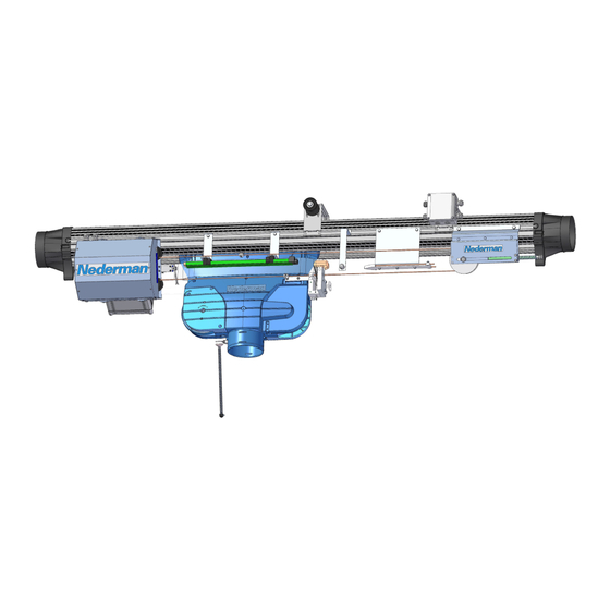
Page 6: Description
Trolley Return Unit 920/1500 Description Components See Figure 1 Component overview, and ‘Table 4-1: Component descriptions’ below. Figure 1 Component overview Suction rail End cover Bus bar SLX3 Motor damper Drive unit driving slot Connection box 1 Guide pulley (on the middle of Balance the rail´s mounting... - Page 7 Trolley Return Unit 920/1500 Component Description Explanation/location CR_BOX_2 3-button control box Emergency stop, Start button and a rotary switch Manual/Automatic return. CR_BOX_3 2-button control box Emergency stop and Start button. Damper Motor Damper motor Closes extraction channel, and counteracts cold downdraft.
-
Page 8: Technical Information
IP 21 Installation Assembly instructions Trolley Return Unit 920/1500 First of all decide if the Trolley Return Unit is to be installed on the Left Hand side (LH) or the Right Hand side (RH) of the 920-rail as seen from the vehicle’s travel direction, see Figure 2. - Page 9 All components included in the return unit are factory assembled for fitting on the LH side of the rail. Follow the steps below to assemble the Trolley Return Unit 920/1500: Remove the suction trolley stop from the rail, see ‘Figure 3’.
- Page 10 Trolley Return Unit 920/1500 Fit the limit switch SL4 on the rear of the drive unit as illustrated, see Figure 6. Adjust the sensor so that the measurement ‘X2’ is 30 mm. RH: Reposition fork. Figure 6 Fit the guide pulley on the rail’s centre most mounting bracket, see Figure 7. If there...
- Page 11 Trolley Return Unit 920/1500 Fit the fixed limit switch SLX on the suction trolley, see Figure 9. Figure 9 Limit switch SLX Engage the balance block catch, see Figure 10. The balance block catch is engaged in position ‘A’. The balance block catch is disengaged in position ‘B’.
- Page 12 See Figure 11 item ‘c’. When the hose is in raised position, the balance block spring force must be adjusted so that the spring is compressed to 50 % of its original length ‘L’ (see the instruction manual 144226 ‘Exhaust Rail System 920/1500’). Figure 11 Disengage the balance block catch.
- Page 13 Trolley Return Unit 920/1500 Fit the disconnection arrow SLX1 in the exhaust rail, see Figure 15. RH: For right hand assembly, disassemble the arrow from the bracket and reassemble it according to Figure 13. Figure 13 Make sure that the suction trolley is located in connection position. Then route the disconnection arrow through the driving slot spring fork on the suction trolley so that the spring fork is then roughly in the centre of the arrow, see Figure 14.
- Page 14 Trolley Return Unit 920/1500 Fit the idler pulley unit in the rail as follows, see Figure 16: RH: Loosen the screws ‘a’, and turn the idler pulley 180°. Refit screws ‘a’ on the other side. Slide in the idler pulley unit into the rail close to the disconnection arrow. Do not tighten the idler pulley to the rail.
- Page 15 Trolley Return Unit 920/1500 While the idler pulley unit is not fixed to the rail, push the idler pulley unit as far as possible towards the end of the rail and fix the idler pulley unit to the rail. Tighten the wire further by adjusting the screw and nuts on the end of the idler pulley unit until the spring is compressed to a 50 mm (2’’) length, see Figure 16.
- Page 16 Fit the motor damper in the channel between exhaust rail and fan. Do not connect Trolley Return Unit 920/1500 to the power network. Connect the system components electrically in accordance with the circuit diagrams and electrical installation instructions, see ‘Appendix A: Cable connections’.
-
Page 17: Description Of Cable And End Marking
Trolley Return Unit 920/1500 WARNING! Risk of electric shock! Work with electric equipment is to be carried out by a qualified electrician. A lockable safety switch shall be installed between the system and the power network. Description of cable and end marking... - Page 18 Trolley Return Unit 920/1500 • 3 Control boxes, Option 1 middle control box, see Appendix B, ‘Circuit diagram 3’. • 3 Control boxes, Option 2 middle control box, see Appendix B, ‘Circuit diagram 4’, which is used to complement an already installed system with an additional middle control box.
- Page 19 Trolley Return Unit 920/1500 Cable W4 Route the cable W4 (embedded cable from limit position SL4) under the extraction channel behind the end stop into connection box 1 and connect in accordance with Appendix B, ‘Circuit diagram 2’. Affix the cable with fasteners and cable ties.
-
Page 20: Electrical Continuous Test (2 Persons Required)
A qualified electrician must perform the installation and the connection to the network. Green-marked components and pink marked cables are included in the suction trolley return and are installed by Nederman’s electricians. Blue-marked components, and yellow-marked cables are not included in the suction trolley return and are installed by a local qualified electrician. -
Page 21: Check Cable W1
Trolley Return Unit 920/1500 5.4.1 Check cable W1 • Check the connection at the Drive Unit terminal X2. All of the wires on cable W1 are individually marked from 1 to 12 and shall be connected to the corresponding number on the terminal X2: i.e. wire marked “1” is connected to terminal X2:1 etc. - Page 22 Trolley Return Unit 920/1500 Test the Disconnection Arrow (SLX1). Make sure the trolley is not connected to the Bus Bar or the Disconnection Arrow. Place the black test probe in terminal 6. Place the red test probe in terminal 1.
- Page 23 Trolley Return Unit 920/1500 Place the black test probe in terminal 6. Place the red test probe in terminal 5. Test the Emergency Stop Button(s) at Control Box 2 and 3 (option) one at a time by push and pull. After each test make sure the button is pulled out (reset).
-
Page 24: Installation Checking
Trolley Return Unit 920/1500 Installation checking WARNING! Risk of electric shock! Work with electric equipment is to be carried out by a qualified electrician. A lockable safety switch shall be installed between the system and the power network. First check the Drive unit fuse set up and transformer voltage setting according to Appendix B, ‘Circuit diagram 1’. -
Page 25: Work Procedure (Normal Operation)
Trolley Return Unit 920/1500 Work procedure (Normal operation) The vehicle drives into connection position. The exhaust hose is pulled down and the nozzle is connected onto the vehicle’s exhaust pipe. Limit position SLX is opened: damper is opened and the fan is activated. -
Page 26: Spare Parts
Other malfunctions, see chapter ‘9 Troubleshooting’ or contact a service technician. Spare parts Contact your nearest authorized distributor or Nederman for advice on technical service or if you require help with spare parts. See also www.nederman.com. Ordering spare parts When ordering spare parts always state the following: •... -
Page 27: Troubleshooting
Trolley Return Unit 920/1500 Troubleshooting Table 9-1: Troubleshooting table Cause Solution The system does not react to Check that the working switch is switched on and that the power fuse is any activity. intact. Measure the power supply after the working switch. Check that the fuse F1/ 2 or 4 A time lag T is intact and that the power supply can be measured after the fuse. -
Page 28: Appendix A: Cable Connections
Trolley Return Unit 920/1500 Appendix A: Cable connections Cable connections overview... -
Page 29: Simple Cable Connections Overview
Trolley Return Unit 920/1500 Simple cable connections overview... -
Page 30: Appendix B: Circuit Diagrams
Trolley Return Unit 920/1500 Appendix B: Circuit diagrams Driving slot circuit diagram ... -
Page 31: Circuit Diagram 1
Trolley Return Unit 920/1500 Circuit diagram 1 ... -
Page 32: Circuit Diagram 2
Trolley Return Unit 920/1500 Circuit diagram 2 ... -
Page 33: Circuit Diagram 3
Trolley Return Unit 920/1500 Circuit diagram 3 ... -
Page 34: Circuit Diagram 4
Trolley Return Unit 920/1500 Circuit diagram 4 ... -
Page 35: Circuit Diagram 5
Trolley Return Unit 920/1500 Circuit diagram 5... -
Page 36: Circuit Diagram 6
Trolley Return Unit 920/1500 Circuit diagram 6... -
Page 37: Circuit Diagram 7
Trolley Return Unit 920/1500 Circuit diagram 7... -
Page 38: Circuit Diagram 8
Trolley Return Unit 920/1500 Circuit diagram 8... -
Page 39: Circuit Diagram 9
Trolley Return Unit 920/1500 Circuit diagram 9 ... -
Page 40: Circuit Diagram 10
Trolley Return Unit 920/1500 Circuit diagram 10 ... - Page 44 www.nederman.com...
Need help?
Do you have a question about the 920/1500 and is the answer not in the manual?
Questions and answers