Table of Contents
Advertisement
Quick Links
Advertisement
Table of Contents

Subscribe to Our Youtube Channel
Related Manuals for Crystal DB477I


Summary of Contents for Crystal DB477I
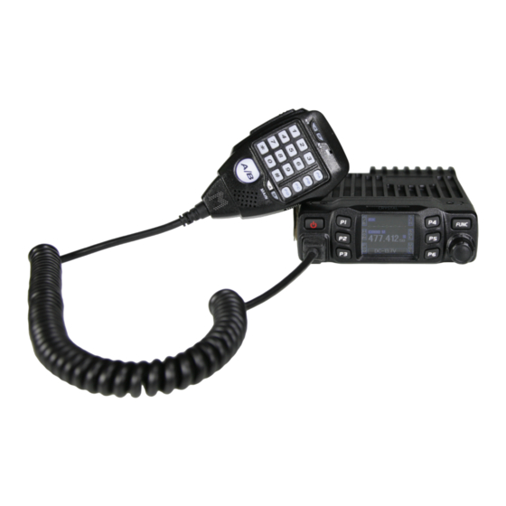
- Page 1 DB477I User Manual www.crystalm.com.au...
-
Page 2: Table Of Contents
CONTENTS Contents ................2 Shortcut Operations .............14 Contents cont ................... 3 Channel scan ................... 14 Accessories ................4 Scan skip ..................14 Initial Installation ..............5 Squelch Off/Squelch Off momentary..........14 Keypad lockout ................14 Mobile installation ................5 Function Menu ..............15 DC Power cable connection ............. 6 Fixed station power supply .............. -
Page 3: Contents Cont
CONTENTS Channel Menu ...............18 Radio Operation and EME Exposure..........30 Electromagnetic Interference/Compatibility........30 RCDT: CTCSS/DCS decode setup ..........18 Aircraft....................30 CTCSS/DCS encode setup .............. 18 Medical Devices ................30 Signaling combination setup ............18 General warnings & Precautions............. 31 Reverse TX/RX ................ -
Page 4: Accessories
Accessories Inclusions FUNC Microphone Mounting bracket Screws Pads Adjusting screws Transceiver DC Power cable with Fuse Holder Non-slip mat Fuse(10A 250V) Optional accessory (sold separately) PC programming cable (CUSBPC) -
Page 5: Initial Installation
Initial Installation Mobile installation To install the transceiver, select a safe, convenient location inside your vehicle that minimizes danger to your passengers and yourself while the vehicle is in motion. Consider installing the unit at an appropriate position so that knees or legs will not strike it during sudden braking of your vehicle. Try to pick a well ventilated location that is shielded from direct sunlight. -
Page 6: Dc Power Cable Connection
Initial Installation DC Power Cable Connection Locate the power input connector as close to the transceiver as possible. Mobile Operation Black The vehicle battery must have a nominal rating of 12V. Never connect the transceiver to a 24V battery. Be sure to use a 12V Connect the DC power cable to the transceiver's power supply vehicle battery that has sufficient current capacity. -
Page 7: Fixed Station Power Supply
Initial Installation To turn on the unit, press the power switch manually while it is illuminated. (While ignition key is at ACC or ON position) When the ignition key is turned to ACC or ON position with the radio's power switch on, the unit turns on automatically and the power switch will be lit. -
Page 8: Replacing Fuses
The transceiver can give excellent results if the antenna authorized Crystal M dealer or an authorized Crystal M service center system and its installation are given careful attention. -
Page 9: Getting Acquainted
Getting Acquainted Microphone Microphone Buttons For voice communications, connect a microphone equipped with an 8-pin modular plug into the modular socket on the front of the main unit. Press firmly on the plug until the locking tab clicks. Attach the supplied microphone hanger in an appropriate location using the screws included in the screw set. -
Page 10: Front Panel Display
Getting Acquainted Display 7 8 11 12 9 13 14 Front panel. FUNC 23 18 19 20 21 22 Functions Functions Power On/Off/Mute Displays the main channel TX or RX status Displays when Automatic power off function is on Displays main channel number in channel mode Displays when set band width for main channel Function key/ function group key Displays when main channel set CTCSS/DCS... -
Page 11: Working Display Mode
Working display mode Changing display modes You can set the radio to work in Amateur Transceiver mode or Professional Transceiver mode. There are also 2 levels operation menu to set functions as you need. It is easy and convenient. FUNC MENU is for set background function, CHAN MENU for set channel function, MINI KEY menu for set self define key, HAND KEY for set self mic define key. -
Page 12: Software
ON. Open up the software and click on this symbol Choose the correct COM port. Choose any of the settings and configure to your needs. To save setting to your DB477I click on this symbol This will write to the unit and save the settings. -
Page 13: Basic Operations
Basic Operations Basic Operations Switching The Power On/Off 2.5k, 5k, 6.25k, ,10k, 12.5k, 20k, 25k, 30k and 50k step size Short press to power on the radio or set automatic power on available for this radio. according the funtion menu, hold for over 2 seconds to power off the radio. -
Page 14: Shortcut Operations
Shortcut Operations Shortcut Operations Channel Scan squelch off/squelch off momentary In channel mode, this function is designed to monitor signal of all In channel mode, this function is designed to monitor signal of all The PX key defined as MON function can set as squelch off/squelch frequency points under each step size off momentary. -
Page 15: Function Menu
Function Menu Function Menu SQL (Squelch level setup) Press & hold FUNC button to activate SELECT MENU Press P4,P6 or turn CHANNEL KNOB to choose through menu list. This function is used for setting RX signal strength, the calling will be Press P5 go directly to bottom of SELECT Menu. -
Page 16: Scan Dwell Time Setup
Function Menu Function Menu SCM (Scan dwell time setup) DIM (Backlight brightness setup) 1. Enter FUNCTION MENU list, choose No.06 function 1. Enter FUNCTION MENU list, choose No.09 function 2. Press the PUSH/CHANNEL KNOB button, the menu value on the LCD 2. -
Page 17: Pilot Frequency
Function Menu Function Menu TBST (Pilot Frequency) (Microphone speaker) This function uses to start repeater. It needs a certain intensity Pilot 1. Enter FUNCTION MENU list, choose No.14 function Frequency to start dormant repeater. As usual,no need to send pilot 2. -
Page 18: Channel Menu
Channel menu TCDT (CTCSS/DCS encode setup) Press & hold FUNC button to activate SELECT MENU Press P4,P6 or turn CHANNEL KNOB to choose through menu list. 1.Enter CHAN MENU, choose No 2 function Press P5 go directly to bottom of SELECT Menu 2. -
Page 19: Reverse Tx/Rx
Channel Menu REV (Reverse TX/RX) OFFSET (Offset frequency and direction setup) When turn of this function, the TX frequency truns to RX frequency 1. Enter CHAN MENU list, choose No.6 function and RX frequency turns to RX frequency. the signaling will also reversed 2. -
Page 20: Busy Channel Lockout
Channel Menu LOCK (Busy Channel Lockout) Busy channel lockout disables transmitting while RX singal is received. Once the channel is busy and you press PTT, the radio will beep as a warning and get back to receiving 1. Enter CHAN MENU list, choose No.8 function 2. -
Page 21: Keypad Menu Setup (Mini Key)
Keypad Menu Setup Press & hold FUNC button to activate SELECT MENU 3. Turn the PUSH/CHANNEL KNOB button to choose setting. Press P4,P6 or turn CHANNEL KNOB to choose through menu list OFF, 1-31 levels of brightness Press P5 go directly to bottom of SELECT Menu 4. -
Page 22: Specifications
Specifications General Receiver (ETSI EN 300 086 standard testing) Narrow Band Frequency Range UHF: 476-477MHz Sensitivity > _ _ 0.35μV Number of Channels 80 Channels (12dB Sinad) Adjacent Channel Channel Spacing 12.5K (Narrow Band) > _ 60dB Selectivity Operating Voltage 13.8V DC - 15% Audio Response... -
Page 23: Trouble Shooting
Trouble shooting Problem Possible Causes and Potential Solutions + and - polarities of power connection are reversed. Connect red lead to plus terminal and black lead to (1) Power is on, but no display minus terminal of DC power supply (2) Fuse is blown Check and solve problem resulting in blown fuse and replace fuse with new fuse (3) No sound comes from speaker... -
Page 24: Attached Chart
Attached Chart 50 groups CTCSS Tone Frequency(Hz) 1024 groups DCS Code. 67.0 79.7 94.8 110.9 131.8 156.7 171.3 186.2 203.5 229.1 69.3 82.5 97.4 114.8 136.5 159.8 173.8 189.9 206.5 233.6 71.9 85.4 100.0 118.8 141.3 162.2 177.3 192.8 210.7 241.8 74.4 88.5 103.5 123.0 146.2 165.5 179.9 196.6 218.1 250.3 77.0 91.5 107.2 127.3 151.4 167.9 183.5 199.5 225.7 254.1... - Page 25 Attached Chart...
-
Page 26: Uhf Channels & Frequencies
UHF channels & frequencies IMPORTANT NOTE: The operaton of your UHF radio in Australia and New Zealand is subject to conditons in the following licenses: In Australia the ACMA Radio communicatons (Citzen Band Radio Statons) and in New Zealand by MED the General User Radio License for Citzen Band Radio. - Page 27 UHF channels & frequencies 476.4375 476.4875...
- Page 28 UHF channels & frequencies 476.4375 476.4875 476.5375 476.5875 476.6375 476.6875 476.7375 476.7875 476.8375 476.8875 477.0325 477.0875...
- Page 29 UHF channels & frequencies 477.0325 477.0875 477.3325 477.3875 Licenses for Repeater Channels 44 & 45 will not be licensed for an additional 6 to 12 months to allow extra time for owners of Channel 5 Emergency repeaters to upgrade equipment to meet the new standards. Channels 1 to 8 and 41 to 48 - Repeater Channels Press the DUPLEX button on your radio to used any available repeaters.
-
Page 30: Australian Broardcasting Requirements
Australian Broardcasting Requirements Transmit and Receive Procedure Medical Devices Your two-way radio contains a transmitter and a receiver. To control Pacemakers your exposure and ensure compliance with the general population/ The Advanced Medical Technology Association recommends that a uncontrolled environment exposure limits, always adhere to the minimum separation of 6 inches (15cm) be maintained between a following procedure: •... -
Page 31: General Warnings & Precautions
Roger Beep foliage and by operating radios indoors or in vehicles. Your DB477I is simplex “one way at a time”. While you are speaking, This is a tone which is automatically transmitted whenever the PTT you can not receive a transmission. -
Page 32: Duplex Operation Via Repeaters And Licence Information
Australian Broardcasting Requirements Channel 5 and 35 (paired for Duplex repeaters) are reserved as emergency channels and should be used only in an emergency. CTCSS and DCS will not operate on channels 5 and 35. A list of currently authorised channels can be obtained from the ACMA website in Australia and the MED website in New Zealand. -
Page 33: Notes
Notes ––––––––––––––––––––––––––––––––––––––––––––––––––––––– ––––––––––––––––––––––––––––––––––––––––––––––––––––––– ––––––––––––––––––––––––––––––––––––––––––––––––––––––– ––––––––––––––––––––––––––––––––––––––––––––––––––––––– ––––––––––––––––––––––––––––––––––––––––––––––––––––––– ––––––––––––––––––––––––––––––––––––––––––––––––––––––– ––––––––––––––––––––––––––––––––––––––––––––––––––––––– ––––––––––––––––––––––––––––––––––––––––––––––––––––––– ––––––––––––––––––––––––––––––––––––––––––––––––––––––– ––––––––––––––––––––––––––––––––––––––––––––––––––––––– ––––––––––––––––––––––––––––––––––––––––––––––––––––––– ––––––––––––––––––––––––––––––––––––––––––––––––––––––– ––––––––––––––––––––––––––––––––––––––––––––––––––––––– ––––––––––––––––––––––––––––––––––––––––––––––––––––––– ––––––––––––––––––––––––––––––––––––––––––––––––––––––– ––––––––––––––––––––––––––––––––––––––––––––––––––––––– ––––––––––––––––––––––––––––––––––––––––––––––––––––––– ––––––––––––––––––––––––––––––––––––––––––––––––––––––– ––––––––––––––––––––––––––––––––––––––––––––––––––––––– ––––––––––––––––––––––––––––––––––––––––––––––––––––––– ––––––––––––––––––––––––––––––––––––––––––––––––––––––– ––––––––––––––––––––––––––––––––––––––––––––––––––––––– ––––––––––––––––––––––––––––––––––––––––––––––––––––––– ––––––––––––––––––––––––––––––––––––––––––––––––––––––– ––––––––––––––––––––––––––––––––––––––––––– ––––––––––––––––––––––––––––––––––––––––––––––... -
Page 34: Technical Assistance
Technical assistance If you need assistance setting up or using your CRYSTAL product now or in the future, call CRYSTAL M Support. Australia TEL: 03 – 8587 8898 FAX: 03 – 8587 8866 Mon-Fri 9am – 5pm AEST Please retain this user guide for future reference. -
Page 35: Warranty Information
Warranty information CRYSTAL MOBILE WARRANTY AGAINST DEFECTS This warranty against manufacturing defects is given by TDJ Australia Pty Ltd ACN 006 385 191). Our contact details are set out in clause 2.7. 1. Consumer guarantee Our goods come with guarantees that cannot be excluded under the Australian Consumer Law. - Page 36 Warranty information 2. Warranty against defects 2.1 This Warranty is in addition to and does not limit, exclude or restrict your rights under the Competition and Consumer Act 2010 (Australia) or any other mandatory protection laws that may apply. Consumer guarantees are a set of rules that apply to goods and services purchased by consumers under the Australian Consumer Law (ACL).
- Page 37 Warranty information 2.4 For repairs outside the warranty period, we warrant our repairs to be free from defects in materials and workmanship for three months from the date of the original repair. We agree to re- repair or replace (at our option) any materials or workmanship which we are satisfied do not meet manufacturers specifications.
- Page 38 (f) goods where the serial number has been removed or made illegal. 4. Warranty period 4.1 We provide the following warranty on Crystal Mobile products. No repair or replacement during the warranty period will renew or extend the warranty period past the period from original date of purchase.
Need help?
Do you have a question about the DB477I and is the answer not in the manual?
Questions and answers