Advertisement
Advertisement
Table of Contents

Related Manuals for AES EPIC 1D


Summary of Contents for AES EPIC 1D
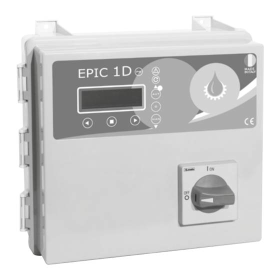
- Page 1 MADE IN ITALY EPIC 1D Installation ad use manual 0,37÷15 RANGE 0,50÷20...
- Page 2 For instructions, 1.2 DESCRIPTION pag. 3 use and maintenance of EPIC 1D. situations and events not considered in this The user should read this manual before operating manual or in the sale documents, please contact 1.3 HANDLING...
-
Page 3: Safety Informations
ATTENTION: ELECTRICAL CONNECTION • (400V ± 10% 50/60Hz x il EPIC 1D -400/...) The line must be protected with an Earth • The control panel must be connected by a qualified electrician in compliance •... -
Page 4: Electrical Connections
Installation Installation EPIC 1D EPIC 1D 3.2 ELECTRICAL CONNECTIONS EPIC 1D 230 EPIC 1D 400 N L C 230 V 400 V 50÷60 Hz 50÷60 Hz 2 3 C 2 3 C... - Page 5 Installation Installation EPIC 1D EPIC 1D 3.3 ADJUSTMENTS AND SETTINGS (INITIALIZATION) CONTROL PANEL TURN ON AUTOTUNING (OBLIGATORY) Step 5 Step 6 Step 7 >LANGUAGE AUTOTUNING: P1 AUTOTUNING: P1 CONFIRM DATA? >ITA PUSH CONFIRM xxxV After making all the electrical connections, initial message to appear on the display.
- Page 6 Installation Installation EPIC 1D EPIC 1D 3.4 ADJUSTMENTS AND SETTINGS (ADVANCED MENU) M01 UTILITY ACCESS TO ADVANCED MENU ACCESS TO FUNCTION MODIFIED PARAMETERS DIP-SWITCH 2 The control panel is set as standard with the dip-switch LANGUAGE >M01 UTILITY 2 in the “OFF” position. To access the “ADVANCED Language selection MENU”...
- Page 7 Installation Installation EPIC 1D EPIC 1D M02 GENERAL CHANGE “MAN” BUTTON (STABLE/UNSTABILE) ACCESS TO FUNCTION MODIFIED PARAMETERS M01 UTILITY >MAN. MODALITY MAN. MODALITY PUMP START DELAY M01 UTILITY >MAN. MODALITY >OFF PUMP STOP DELAY >M02 GENERAL MAN. MODALITY M01 UTILITY >EXIT...
- Page 8 Installation Installation EPIC 1D EPIC 1D M03 NET CONTROL ACCESS TO FUNCTION MODIFIED PARAMETERS CHANGE MAXIMUM VOLTAGE M03 NET CONTROL >MAX VOLTAGE MAX VOLTAGE NOMINAL VOLTAGE M02 GENERAL >MAX VOLTAGE >110 MINIMUM VOLTAGE >M03 NET CONTROL MAXIMUM VOLTAGE NOMINAL FREQUENCY...
- Page 9 Installation Installation EPIC 1D EPIC 1D M04 PUMP 1 ACCESS TO FUNCTION MODIFIED PARAMETERS CHANGE MINIMUM AMPERAGE AUTOTUNING M04 PUMP 1 >MIN AMPERAGE MIN AMPERAGE It allows the self-learning of the data to be carried out again >M04 PUMP 1 >MIN AMPERAGE...
-
Page 10: Operation
Installation Installation EPIC 1D EPIC 1D M06 PROGRAM ACCESS TO FUNCTION MODIFIED PARAMETERS SELF HOLDING M06 PROGRAM >SELF HOLDING SELF HOLDING OPERATION M04 PUMP 1 >SELF HOLDING >ON Emptying selection “EMPTY” or filling ”FILL“ >M06 PROGRAM TYPE Selection of clear or dirty water types... - Page 11 Installation Installation EPIC 1D EPIC 1D M07 SENSOR (sensor/trasducer 4÷20 mA) ACCESS TO FUNCTION MODIFIED PARAMETERS SET MINIMUM LEVEL M07 SENSOR >MIN LEVEL MIN LEVEL PARAMETERS M06 PROGRAM >MIN LEVEL 005.5 >005.0 Setting unit of measure (mt/bar) >M07 SENSOR FULL SCALE Set the full scale value specified by the manufacturer of the sensor used (serial value 160.0)
- Page 12 Installation Installation EPIC 1D EPIC 1D M08 TIMER PUMP 1 STOP ACCESS TO FUNCTION MODIFIED PARAMETERS M07 SENSOR >P1 STOP P1 STOP ENGAGE TIMER T1 M07 SENSOR >P1 STOP 020.0 >020.0 TIMER T1 ON >M08 TIMER Setting the working minutes of the pump...
- Page 13 Installation Installation EPIC 1D EPIC 1D 3.5 TRIMMER SETTINGS To change manually the threshold protections, PROTECTION DELAY TIMER T1 OFF interrupt the power supply to the control The pump protection switching panel and work on the trimmers, please delay has been set at 5 sec.
-
Page 14: General Use
General use EPIC 1D EPIC 1D 4.1 KEYPAD AND LIGHTS INDICATIONS CONTROL PANEL blue light indicating power network presence and powered panel. ALARM red light to indicate a general alarm and pump stop. (min e max Amp, min e max V, min e max level, motor klixon, water in oil chamber, phase failure). - Page 15 General use General use EPIC 1D EPIC 1D 4.2 ALARMS The control panel signals a series of alarms that All alarms are displayed on the panel (red LED ALARM WITH STOP PUMP may occur during operation. Some of these stop flashing), while the display shows the code/alarms the pumps, while others are only displayed.
-
Page 16: Typical Installations
General use General use EPIC 1D EPIC 1D 4.3 TYPICAL INSTALLATIONS 4÷20 4÷20 4÷20 4÷20 start/stop min lev. start/stop start start/stop stop 4÷20 4÷20 4÷20 4÷20 start/stop start/stop 4÷20 mA piezo 4÷20 mA start/stop 4÷20 input for 4÷20 mA sensor or pressure transducer pressure transducer 4÷20... -
Page 17: Maintenance
• Electromagnetic 5.2 SERVICE directive compatibility 2006/95/CE directive EPIC 1D does not require any routine maintenance DANGER! 2004/108/CE provided that their working limits are observed. Make sure that EPIC 1D is Any maintenance operations must be performed disconnected from the power... - Page 18 Notes Notes EPIC 1D EPIC 1D...
- Page 19 Tel: 01842 819130 Email: sales@automatedenvironmentalsystems.co.uk www.automatedenvironmentalsystems.co.uk...
Need help?
Do you have a question about the EPIC 1D and is the answer not in the manual?
Questions and answers
Alarm 1 minimum voltage is showing. What possible causes and actions?