
Related Manuals for Vetus GHX

Summary of Contents for Vetus GHX
- Page 1 Installation manual ENGLISH Generator Sets 6 - 24 kVA Copyright © 2016 Vetus b.v. Schiedam Holland 380602.01...
-
Page 2: Table Of Contents
Electrical installation Electrical system engine (12 volt) 4.1.1 Remote control panel Electrical system generator Technical data Overall dimensions Consult the owner’s manual for Operation, Maintenance, Trouble shooting and detailed Technical data. vetus® Installation manual Generator Sets GHX / GLX 380602.01... -
Page 3: Safety Information
• Do not keep using the generator set if anomalies are detected. • In case of anomaly, stop immediately the engine or reduce the load as much as possible. Start again only when normal condition are restored. vetus® Installation manual Generator Sets GHX / GLX 380602.01... - Page 4 It is the responsibility of the purchaser (whether boat builder or dealer) of a VETUS generator set to select the appropri- ate package for a given installation. Making such a selection requires knowledge of the boat, including intended use, intended duty cycle all of which is in the exclusive possession of the purchaser.
-
Page 5: Engine Lifting
Assure that the spacer rod is in ‘good condition‘ and strong enough to with- stand the weight. MIN. 150 cm (5 ft) The lifting hooks are engineered only to lift the WARNING generator set without any extra weights! vetus® Installation manual Generator Sets GHX / GLX 380602.01... -
Page 6: Introduction
When the temperature of the engine stabilizes at a temperature higher than normal it might be necessary to bleed the coolant circuit. 2.2.1 Bleeding the coolant circuit: • Switch off the engine of the generator set. • Open the expansion tank cap to let the air escape. vetus® Installation manual Generator Sets GHX / GLX 380602.01... -
Page 7: Long Engine Storage - Inactivity
• If no anomalies bring the engine to its operating temperature, 70 - 80 °C (158 - 176 °F). Verify that there is no air in the coolant circuit – bleed the air from coolant circuit if necessary. • Turn off the engine and check again the engine oil level and coolant level. • Verify for tightening. vetus® Installation manual Generator Sets GHX / GLX 380602.01... -
Page 8: Generator Set Requirements
IMPORTANT Vetus will not honour any warranty claim for engine damage as a result of water entry. When selecting a location for the generator set take into consideration that there is sufficient room for carrying out maintenance work. -
Page 9: Generator Set Compartment Ventilation
Air outlets should be at the top of the engine room to remove the hottest air. An engine room blower (optional) should be used as an extraction ventilator to remove air from the engine room. Such air intake should be positioned as low as possible. vetus® Installation manual Generator Sets GHX / GLX 380602.01... - Page 10 ( 19 sq.in. ) GLX 20 2.6 m /min ( 93 cu.ft/min ) 146 cm ( 23 sq.in. ) GLX 24 3.2 m /min ( 111 cu.ft/min ) 175 cm ( 27 sq.in. ) vetus® Installation manual Generator Sets GHX / GLX 380602.01...
-
Page 11: Fuel Connection
The max. fuel pump suction pressure head is around 1.5 m (60 inches) take care when ATTENTION! install the fuel line. ATTENTION! Air leaks or narrow needs on fuel line could provoke engine stop. vetus® Installation manual Generator Sets GHX / GLX 380602.01... -
Page 12: Fuel Connections
We recommend a 10 micron, fuel lter 190 l/h (42 Imp. gph, 50 US gph) per hour rated filter Vetus type 330 VTEB. This will help to filter out contaminants in diesel fuel. Select a suitable position in the fuel system between the fuel supply... -
Page 13: Raw Water Circuit
- Hose clamps and - 2 metre hose For inner diameter: Generator set model Diameter GHX 8, GHX 9, GHX 14, GHX 17, GHX 24,GLX 6, GLX 7, GLX 14, GLX 17 19 mm in. ) GLX 20, GLX 24 25 mm ( 1 in. -
Page 14: Raw Water Inlet
10 knots or more opening facing forward vetus® Installation manual Generator Sets GHX / GLX 380602.01... -
Page 15: Raw Water Inlet Hose
Be sure to secure hose connections with hose clamps. Secure hose to prevent contact with any moving parts of the engine. The suction hose is to be kept as short as possible. Raw water plumbing should exclude IMPORTANT bends as much as possible. vetus® Installation manual Generator Sets GHX / GLX 380602.01... -
Page 16: Seawater Strainer
Use sealing compound or tape at all connections to prevent air leaks. The neoprene impeller in the raw water pump should never be run dry. All hose joints should be double clamped with 304/316 stainless-steel hose clamps. T-bolt clamps are even better but must be 304/316 stainless. vetus® Installation manual Generator Sets GHX / GLX 380602.01... -
Page 17: Exhaust System
3.4.1 Wet exhaust systems The exhaust system of VETUS generator sets is water injected. The cooling water that has passed the heat exchanger is mixed with the exhaust gases. Temperature and volume of the gases are thereby reduced considerably so that a rubber exhaust hose can be used. -
Page 18: Prevention Of Siphoning
Installation manual Generator Sets GHX / GLX 380602.01... -
Page 19: Dimensional Recommendations
Unusual cranking and/or cranking interruptions must be monitored and the muffler drained before excessive water build-up occurs. This may be made more convenient by installing a suitable, non-corrosive valve at the muffler drain fitting. vetus® Installation manual Generator Sets GHX / GLX 380602.01... -
Page 20: Electrical Installation
4.1.1 Remote control panel If required a remote control panel can be connected to the gen- erator set. Remote control panel complete with 6 meter (19 ft 8in) connec- tion cable, Vetus art.code: MPRGEN. vetus® Installation manual Generator Sets GHX / GLX 380602.01... -
Page 21: Electrical System Generator
Maximum current in Amps at number Maximum current in Amps at number Cross-section of current carrying conductors of current carrying conductors in mm cross-section 2 or 3 2 or 3 vetus® Installation manual Generator Sets GHX / GLX 380602.01... -
Page 22: Technical Data
275 kg 395 kg Model : GLX 14 TIC GLX 20 TIC GHX 9 SIC GHX 17 SIC GLX 7 SIC GLX 17 SIC GHX 17 TIC GLX 17 TIC GLX 24 TIC Power 14 kVA 20 kVA 9 kW... -
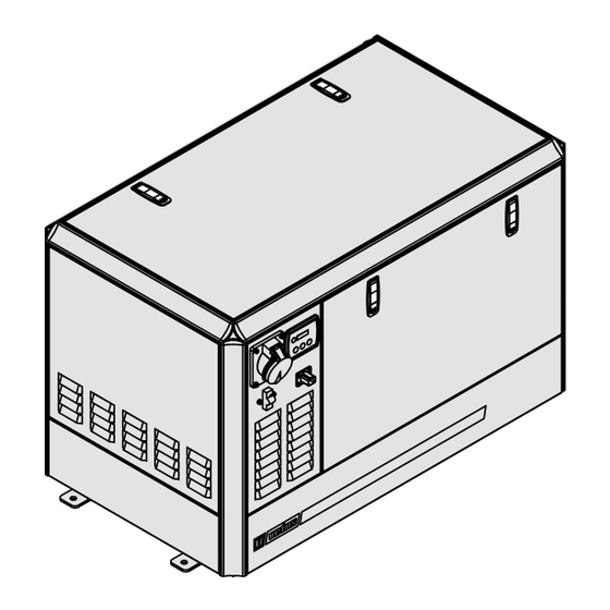
Page 23: Overall Dimensions
GHX 8 SIC / TIC GHX 9 SIC ”) ”) ”) ”) ”) ”) ”) 1082 1042 GHX 14 SIC / TIC GHX 17 SIC / TIC ”) ”) ”) (41”) ”) ”) ”) 1172 1132 GLX 14 SIC / TIC GLX 17 SIC / TIC ”) - Page 24 FOKKERSTRAAT 3125 SCHIEDAM HOLLAND TEL.: 4377700 TELEFAX: +31 10 4372673 - 4621286 - E-MAIL: sales@vetus.nl - INTERNET: http://www.vetus.com Printed in the Netherlands 380602.01 2016-10...
Need help?
Do you have a question about the GHX and is the answer not in the manual?
Questions and answers