Table of Contents
Advertisement
Advertisement
Chapters
Table of Contents

Related Manuals for Vetus GHX8

Summary of Contents for Vetus GHX8
- Page 1 GHX GLX Generator Sets Owner’s Manual 380502.01...
- Page 3 Please enter the serial numbers here. These numbers should be quoted when inquiring about Customer Ser- vice, Repairs or Spare Parts (see page 12). We reserve the right to make any changes without previous notice. Copyright © 2018 Vetus B.V. Schiedam Holland...
- Page 4 Unauthorized generator set modifications will invalidate any liability claims against the manufacturer for resultant damage. For the Guarantee Conditions, see the Vetus Diesel ‘Service and War- ranty Manual’ . Manipulations of the injection and regulating system may also influ- ence the performance of the engine, and its emissions.
-
Page 5: Table Of Contents
Inhoud Safety measures Winter Lay-up Warning indications Preparation for Winter Preventing fire and explosion Preparation for Summer Prevention of injury Fault Finding, generator When problems occur General Introduction Technical data Description of the generator set Winding resistances Connection and control panel Operating Media Remote control panel Identification of the generator set... -
Page 6: Safety Measures
1 Safety measures Warning indications Warning indications The following warning indications are used in this manual in the context of safety: Symbols anger aution Indicates that great potential danger exists Indicates that the usage procedures, actions Indicates that the relevant procedure that can lead to serious injury or death. -
Page 7: Preventing Fire And Explosion
1 Safety measures Preventing fire and explosion ire risk • Do not smoke if refuelling. • Do not fill the fuel tank while the engine is • Connecting (emergency) extra starting bat- running! tery • Avoid spilling fuel on hot surfaces. Spilled Only refuel with the engine stopped. -
Page 8: Prevention Of Injury
1 Safety measures Prevention of injury • The moving parts of the engine are dan- • Satisfy yourself that everything is in order • Remove any tool used to turn the engine gerous. Never touch moving parts of the before the engine is started again! over. - Page 9 1 Safety measures Prevention of injury • Be careful with battery acid! • Make sure that you are wearing suitable If battery acid comes in contact with the clothing before starting work! eyes or skin, rinse the affected part imme- For your own safety you will most likely diately with copious amounts of water.
-
Page 10: When Problems Occur
1 Safety measures When problems occur When the engine stops suddenly: lf the engine overheats: If the fan belt is broken: If the engine stops suddenly, do not start it If the engine should overheat, do not switch Immediately stop the engine. If an engine is again immediately. -
Page 11: Introduction
2 Introduction Dear customer, Vetus generator sets are designed for marine We have endeavoured to highlight any differ- We are available to help with any additional application. Consequently, a wide range of ences so that you will able to locate the oper- inquiries. -
Page 12: Description Of The Generator Set
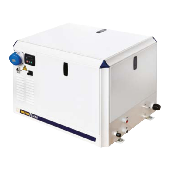
3 Description of the generator set Connection and control panel Single Phase Generator 1 Connection panel for single phase generator set 2 Control panel for single phase generator set 1 Power socket 5 Navigation buttons menu 2 Circuitbreaker 6 Display 3 Control/operation panel 7 Stop / Reset Mode 4 Connection for remote control panel... - Page 13 3 Description of the generator set Connection and control panel Three Phase Generator 3 Connection panel for three phase generator set 4 Control panel for three phase generator set 1 Power socket 5 Navigation buttons menu 2 Connection for remote control panel 6 Stop / Reset Mode 3 Control/operation panel 7 Display...
-
Page 14: Remote Control Panel
See the ‘Overall Dimensions’ drawing for the identification of the most important genera- tor set connections. 1 Alarm accept The Vetus engine serial number and perfor- 2 Stop mance data are printed on the engine data To identify specific engine components, con- 3 Indication ‘Generator in operation’... -
Page 15: Operation
4 Operation General guidelines General Guidelines for Use Following the recommendations below will result in a longer operat- ing life, better performance and more economical operation of your generator set. • Carry out the maintenance described regularly, including the ‘Daily Procedure before Starting’... -
Page 16: Initial Operation, Running-In
4 Operation Initial Operation, Running-in Initial Operation - Engine Running-in Before starting the engine for the first time, carry out the following op- In order to achieve a long operating life for your engine, take care with erations: the following for the first 50 operating hours: •... -
Page 17: Starting
4 Operation Starting Check the following points before starting: Starting After a starting command the starting procedure, pre-heating - start- • Engine oil level ing, will run completely automatically. Starting, at the generator set • Coolant level Press the button ( I ) at the generator panel to •... - Page 18 4 Operation Running 1500 Motortoerental Generator-spanning Generator-frequentie 50.0 16.2 Motor-draaiuren Accuspanning 13.8 1 Single phase generator set 2 Three phase generator set During operation of the generator set on the control panel information During operation of the generator set on the control panel information can be requested.
-
Page 19: Running
4 Operation Running If one or more of the following faults occur, the generator set will be arning switched off automatically: Avoid running on no load or very light load for extended periods. - low oil pressure, - over temperature coolant, This can lead to carbon deposits in the combustion chambers and - over temperature exhaust, incomplete combustion of fuel. -
Page 20: Stopping
4 Operation Stopping Stopping Stopping when the Electrical System (12 Volt) breaks down. Switch off all the ship’s electrical consumers. When the electrical system (12 Volt) breaks down, the engine will stop immediately. Allow the generator set to run for about 1 minute without load. When the generator set is not going to be used for a longer period of Press at one of the panels the time, it is recommended that the seacock is closed and the main switch... -
Page 21: Maintenance
5 Maintenance Introduction Introduction Keep record of the following information in the logbook and/or the ‘Service and Warranty Manual’: The following guidelines should be observed for daily and periodic maintenance. Perform each function at the indicated time interval. - Total engine hours (reading engine running hours on control panel). The intervals stated are for normal operational conditions. -
Page 22: Maintenance Schedule
5 Maintenance Maintenance schedule Every 10 hours or daily, before starting page. Every 100 hours, at least once every year page Check engine oil level Drain water from fuel filter Check coolant level Engine oil change Check water strainer Replace oil filter Battery, cables and cable connections After the first 50 hours page... - Page 23 It is possible that not all maintenance work described will be re- quired on your generator set, this depends on the type of engine. anger Consult the service manual, work to be carried out by a Vetus deal- Stop the engine before carrying out any maintenance work.
-
Page 24: Check Engine Speed/Adjust Fuel Pump
5 Maintenance Check engine Speed/Adjust Fuel Pump Every 500 operating hours Checking the Engine Speed The speed of the generator will decrease as the load increases. So ad- The frequency of the mains voltage is not the same all over the world. just the generator as follows: This frequency can either be 50 or 60 Hz. - Page 25 Reducing the speed Increasing the speed Reducing the speed 1 Adjusting the GHX8, GHX9, GHX14, GHX17, GLX6 and GLX7 2 Adjusting the GHX24, GLX14 and GLX17 Fuel Pump Fuel Pump • Unscrew both lock nuts and adjust the set screws until the correct •...
- Page 26 5 Maintenance Check engine Speed/Adjust Fuel Pump Every 500 operating hours. Increasing the speed Reducing the speed 3 Adjusting the GLX20 and GLX24 Fuel Pump • Unscrew both lock nuts and adjust the set screws until the correct speed has been reached. Then tighten up the lock nuts again. •...
- Page 27 5 Maintenance Bleeding the fuel system 4 Bleeding Proceed as follows if it is necessary to bleed • Open the bleeding nipple on the fuel filter. • Press the button switching ‘ON’ (1), the fuel the fuel system: lift pump will feed the fuel system, the en- Take the auxiliary starter relay from the relay gine will not be started.
-
Page 28: Generator
5 Maintenance Generator Every 1000 operating hours. General Cleaning the generator The generator and AVR (Automatic Voltage Regulator) should be kept as clean as possible. Many electrical faults can be caused by dirt collect- ing. Remove any dirt and dust from the generator. Blow through the generator using oil-free compressed air. -
Page 29: Winter Lay-Up
6 Winter Lay-up Preparation for Winter Preparation for Summer Preparation for Winter Preparation for Summer Consult the separate engine Manual for taking it out of service for the Consult the separate engine Manual for preparation for use again at winter. the start of the summer cruising season. -
Page 30: Fault Finding, Generator
7 Fault Finding, generator General Fault Finding Table 1 No load, no voltage When a fault occurs, check the following before carrying out the tests in the Table: Possible fault Remedy Voltage Regulator (AVR) faulty. Replace the Voltage regulator • The circuit breaker is ‘ON’ . (AVR). - Page 31 7 Fault Finding, generator Fault Finding Table 2 Low voltage 4 Voltage oscillates Possible fault Remedy Possible fault Remedy Incorrect voltage setting of volt- Adjust to the correct voltage. Incorrect Voltage Regulator (AVR) Readjust the stability. age regulator. stability setting. Under frequency protection not Check/adjust the setting of the Engine runs irregularly due to...
-
Page 32: Technical Data
8 Technical data Type GHX 8 SIC GHX 14 SIC GHX 24 SIC GLX 6 SIC GLX 14 SIC GHX 8 TIC GHX 14 TIC Generator Specifications Mark Sincro Sincro Sincro Sincro Sincro Sincro Sincro Type SKM 160 CA2 SKM 160 LA2-1 SKM 160 WA2-1 SKM 160 SA1 SKM 160 MA1... - Page 33 8 Technical data GHX 24 TIC GLX 14 TIC GLX 20 TIC GHX 9 SIC GHX 17 SIC GLX 7 SIC GLX 17 SIC GHX 17 TIC GLX 17 TIC GLX 24 TIC Sincro Sincro Sincro Sincro Sincro Sincro Sincro Sincro Sincro Sincro...
- Page 34 32 A 63 A 100 A 25 A 63 A 12.5 A 20 A (63 A) (125 A) (16 A) (32 A) Engine Specifications Mark Vetus/Mitsubishi Type M2.18 M3.29 M4.45 M3.29 M4.45 M2.18 M3.29 General Nominal speed, RPM 3000 3000...
- Page 35 63 A 150 A 40 A 40 A 63 A (63 A) (32 A) (50 A) (32 A) (80 A) (25 A) (25 A) (32 A) Vetus/Mitsubishi Vetus/Mitsubishi Vetus/Hyundai Vetus/Hyundai M4.45 M4.45 VH4.65 M2.18 M3.29 M3.29 M4.45 M3.29 M4.45 VH4.65...
-
Page 36: Winding Resistances
8 Technical data Winding resistances Type generator SKM 160 LA2 / LA2-1 WA2-1 GHX 8 SIC GHX 14 SIC GLX 6 SIC GLX 14 SIC GHX 14 TIC GLX 14 TIC GLX 20 TIC For generator set model GHX 8 TIC GHX 17 SIC GHX 24 SIC GLX 7 SIC... -
Page 37: Operating Media
9 Operating Media Operating Media These are • Engine oil • Diesel fuel • Coolant fluid Consult the relevant engine Manual for specifications and quantities of the liquids above. -
Page 38: Wiring Diagrams
10 Wiring diagrams Single Phase Generator GHX 8, 9 SIC (M2.18) GHX 14, 17 SIC (M3.29) GLX 6, 7 SIC (M3.29) Control module (3110) Generator Volts Fuel Auxiliary pump start relay relay Remote control panel Blue /White Yellow /White Yellow Orange Violet White... -
Page 39: M4.45
10 Wiring diagrams Single Phase Generator GHX 24 SIC (M4.45) GLX 14, 17 SIC (M4.45) Generator Control module (3110) Volts Fuel pump relay Remote control panel Blue /White Yellow /White Yellow Orange Violet White Black Plug 'A' Black Socket 'A' Socket 'C' Plug 'C' Pre-... -
Page 40: M2.18
10 Wiring diagrams Three Phase Generator GHX 8 TIC (M2.18) GHX 14, 17 TIC (M3.29) FROM GENERATOR TO LOAD Generator current Generator volts Control module (4610) Fuel Auxiliary pump start relay relay Remote control panel Blue /White Yellow /White Yellow Orange Violet White... - Page 41 10 Wiring diagrams Three Phase Generator GHX 24 TIC (M4.45) GLX 14, 17 TIC (M4.45) FROM GENERATOR TO LOAD Generator current Generator volts Control module (4610) Fuel Remote control panel pump relay Blue /White Yellow /White Yellow Orange Violet White Black Black Plug 'A'...
- Page 42 10 Wiring diagrams Three Phase Generator GLX 20, 24 TIC (VH4.65) FROM GENERATOR TO LOAD Generator current Generator volts Control module (4610) Fuel Remote control panel pump relay Blue /White Yellow /White Yellow Orange Violet White Black Black Plug 'A' Socket 'A' Socket 'C' Plug 'C'...
- Page 44 10 Wiring diagrams Single Phase Generator SKM 160 CA2 GHX 8 SIC GHX 9 SIC Single Phase Generator SKM 160 LA2-1 GHX 14 SIC GHX 17 SIC U2-U3 V2-V3 W2-W3 L1 (U) AVR BL4-U L2 (V) L3 (W) STATOR U1-W4 V1-U4 W1-V4 L1 L2(N)
- Page 45 10 Wiring diagrams Single Phase Generator SKM 160 SA2 GLX 6 SIC GLX 7 SIC Single Phase Generator SKM 160 MA1 GLX 14 SIC GLX 17 SIC AVR BL4-U L1 L2(N) L1 L2(N) SINGLE PHASE, SINGLE PHASE, SENSING STATOR SENSING STATOR 0-230 230 V - 50 Hz...
- Page 46 10 Wiring diagrams Three Phase Generator SKM 160 MA2 GHX 14 TIC GHX 17 TIC L1 (U) AVR BL4-U L3 (W) L2 (V) STATOR THREE PHASE, SENSING SENSING THREE PHASE, 400 V - 50 Hz 0-400 0-230 230 V - 50 Hz 415 V - 60 Hz 240 V - 60 Hz GREY...
- Page 47 10 Wiring diagrams Three Phase Generator SKM 160 CA2 GHX 8 TIC Three Phase Generator SKM 160 MA4 GLX 14 TIC GLX 17 TIC L1 (U) U4-V4-W4 U2-U3 V2-V3 W2-W3 AVR BL4-U STATOR L3 (W) L2 (V) U2-U3 V2-V3 W2-W3 THREE PHASE, 400 V - 50 Hz SENSING...
-
Page 48: Overall Dimensions
11 Overall dimensions ø 13 ( ”) (4x) - Page 49 GLX 6 SIC GLX 7 SIC ”) ”) ”) ”) ”) ”) ”) GHX 8 SIC / TIC GHX 9 SIC ”) ”) ”) ”) ”) ”) ”) 1082 1042 GHX 14 SIC / TIC GHX 17 SIC / TIC ”) ”) ”)
- Page 52 F O K K E R S T R A AT 5 7 1 - 3 1 2 5 B D S C H I E D A M - H O L L A N D b. v.
Need help?
Do you have a question about the GHX8 and is the answer not in the manual?
Questions and answers