Table of Contents
Advertisement
Advertisement
Table of Contents

Subscribe to Our Youtube Channel
Related Manuals for Global Fire ORION 4


Summary of Contents for Global Fire ORION 4
- Page 1 Manufacturers of Fire Detection Equipment ORION - 2, 4, 8 ZONE FIRE ALARM CONTROL PANEL INSTALLATION, OPERATION AND MAINTENANCE MANUAL - 10/2011 ORION 2, 4, 8 Zone Fire Alarm Control Panel INSTALLATION, OPERATION AND MAINTENANCE MANUAL Version - 10/2011 www.globalfire.pt...
- Page 2 Manufacturers of Fire Detection Equipment ORION - 2, 4, 8 ZONE FIRE ALARM CONTROL PANEL INSTALLATION, OPERATION AND MAINTENANCE MANUAL - 10/2011 EN54 INFORMATION In accordance with EN 54-2 clause 13.7, the maximum number of sensors and/or manual call points in this panel, will not exceed 512 units.
-
Page 3: Optional Interfaces
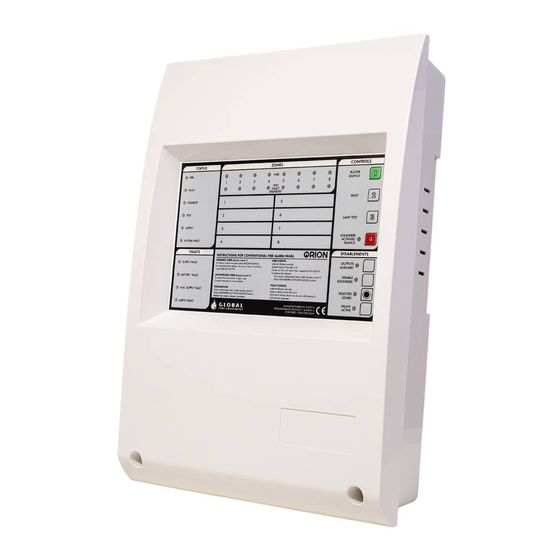
Manufacturers of Fire Detection Equipment ORION - 2, 4, 8 ZONE FIRE ALARM CONTROL PANEL INSTALLATION, OPERATION AND MAINTENANCE MANUAL - 10/2011 Overview The ORION is a 2, 4 and 8 Zone microprocessor controlled conventional Fire Alarm Control Panel with all the functions necessary to control small and medium size fire detection installations. -
Page 4: Important Safety Notes
Manufacturers of Fire Detection Equipment ORION - 2, 4, 8 ZONE FIRE ALARM CONTROL PANEL INSTALLATION, OPERATION AND MAINTENANCE MANUAL - 10/2011 Important Safety Notes This equipment must only be installed and maintained by a suitably qualified and technically competent person. This equipment must have an Earth Connection. -
Page 5: Cable Types
Manufacturers of Fire Detection Equipment ORION - 2, 4, 8 ZONE FIRE ALARM CONTROL PANEL INSTALLATION, OPERATION AND MAINTENANCE MANUAL - 10/2011 Cable Types System wiring should be installed in accordance with National Standards and wiring regulations. To protect against electrical interference we recommend the use of screened cables throughout the system. Separate cables should be used for sounder and detection circuits, the use of multi-core cables to carry sounder circuits and detector circuits is not recommended. -
Page 6: Sounder Circuit Wiring
Manufacturers of Fire Detection Equipment ORION - 2, 4, 8 ZONE FIRE ALARM CONTROL PANEL INSTALLATION, OPERATION AND MAINTENANCE MANUAL - 10/2011 Sounder Circuit Wiring There are two conventional sounder circuits available on the Orion. The maximum current available for sounders is (500 mA) per circuit. - Page 7 Manufacturers of Fire Detection Equipment ORION - 2, 4, 8 ZONE FIRE ALARM CONTROL PANEL INSTALLATION, OPERATION AND MAINTENANCE MANUAL - 10/2011 Outputs Auxiliary Power 28V DC max 300 mA, short circuit protected, supervised. The output is protected against short circuit by an electronic fuse which resets when the fault is cleared and the panel is reset.
-
Page 8: Connecting The Panel
Manufacturers of Fire Detection Equipment ORION - 2, 4, 8 ZONE FIRE ALARM CONTROL PANEL INSTALLATION, OPERATION AND MAINTENANCE MANUAL - 10/2011 Connecting the Panel Before connecting zone or sounder cables, power up the control panel with the Active EOL connected to the zone inputs and the EOL resistors for the sounder lines connected. - Page 9 Manufacturers of Fire Detection Equipment ORION - 2, 4, 8 ZONE FIRE ALARM CONTROL PANEL INSTALLATION, OPERATION AND MAINTENANCE MANUAL - 10/2011 Commissioning The ORION is supplied ready to operate as a standard conventional Fire Alarm control panel. Optional functions and their programming are described in the next section. If required they may be programmed before continuing with the commissioning.
- Page 10 Manufacturers of Fire Detection Equipment ORION - 2, 4, 8 ZONE FIRE ALARM CONTROL PANEL INSTALLATION, OPERATION AND MAINTENANCE MANUAL - 10/2011 Testing Field Equipment Testing Smoke Detectors 1º Set zones to Test mode 2º Introduce test smoke into the detector 3º...
- Page 11 Manufacturers of Fire Detection Equipment ORION - 2, 4, 8 ZONE FIRE ALARM CONTROL PANEL INSTALLATION, OPERATION AND MAINTENANCE MANUAL - 10/2011 Operating & Programming The Panel The ORION has a number of programmable options to help the engineer customize the system to meet the customer's requirements.
- Page 12 Manufacturers of Fire Detection Equipment ORION - 2, 4, 8 ZONE FIRE ALARM CONTROL PANEL INSTALLATION, OPERATION AND MAINTENANCE MANUAL - 10/2011 Level 3: Engineer controls for use by trained and competent personnel only Is accessed from Level 1 and allows: Programming of coincidence Setting delay timer System Test...
-
Page 13: Programmable Options
Manufacturers of Fire Detection Equipment ORION - 2, 4, 8 ZONE FIRE ALARM CONTROL PANEL INSTALLATION, OPERATION AND MAINTENANCE MANUAL - 10/2011 Programmable Options Coincidence: After entering access level 3, using the code provided for this effect, press the OUTPUTS AUXILIARY button in the disablements area of the control panel. -
Page 14: Delay Setting
Manufacturers of Fire Detection Equipment ORION - 2, 4, 8 ZONE FIRE ALARM CONTROL PANEL INSTALLATION, OPERATION AND MAINTENANCE MANUAL - 10/2011 Delay setting To set the delay time, press the DELAYS ACTIVE. After pressing button the associated LED will be ON. The delay time will shown using the first 4 ZONE FIRE ZONE LEDS. -
Page 15: The Panel Buttons
Manufacturers of Fire Detection Equipment ORION - 2, 4, 8 ZONE FIRE ALARM CONTROL PANEL INSTALLATION, OPERATION AND MAINTENANCE MANUAL - 10/2011 The Panel Buttons STATUS ZONES CONTROLS FIRE FIRE BUZZER SILENCE TEST FAULT FAULT DISABLED RESET DISABLED TEST LAMP TEST SUPPLY SOUNDERS ACTIVATE/... - Page 16 Manufacturers of Fire Detection Equipment ORION - 2, 4, 8 ZONE FIRE ALARM CONTROL PANEL INSTALLATION, OPERATION AND MAINTENANCE MANUAL - 10/2011 FAULTS SUPPLY FAULT This LED will be ON whenever the Main Supply has been removed or has dropped below 20 Volts.
- Page 17 Manufacturers of Fire Detection Equipment ORION - 2, 4, 8 ZONE FIRE ALARM CONTROL PANEL INSTALLATION, OPERATION AND MAINTENANCE MANUAL - 10/2011 DISABLEMENTS These buttons are only active at access levels 2 or 3. They can perform different functions depending on the present panel mode of operation. At Access Level 2 (USER MODE) These buttons have a toggle action.
- Page 18 Manufacturers of Fire Detection Equipment ORION - 2, 4, 8 ZONE FIRE ALARM CONTROL PANEL INSTALLATION, OPERATION AND MAINTENANCE MANUAL - 10/2011 Troubleshooting - Fault Indications Troubleshooting work of any fault on the panel should only be carried out by qualified technicians. General Fault The General fault LED is illuminated whenever there is a fault on the system.
-
Page 19: Standby Battery Calculation
Manufacturers of Fire Detection Equipment ORION - 2, 4, 8 ZONE FIRE ALARM CONTROL PANEL INSTALLATION, OPERATION AND MAINTENANCE MANUAL - 10/2011 Standby Battery Calculation Min battery capacity 2 x 2 Ah 12 V DC Max Battery capacity 2 x 7 Ah 12 V DC Always use Lead- acid VRLA Batteries The battery Ah required for a given installation is calculated from the following formula: Standby time... -
Page 20: Technical Specifications
Manufacturers of Fire Detection Equipment ORION - 2, 4, 8 ZONE FIRE ALARM CONTROL PANEL INSTALLATION, OPERATION AND MAINTENANCE MANUAL - 10/2011 Technical Specifications POWER SUPPLY SPECIFICATION MAINS SUPPLY VOLTAGE 230V +10%/ -15% INTERNAL POWER SUPPLY Min. 21 V DC - Max. 30 V DC (28.5 V DC nominal) Max. - Page 21 INSTALLATION, OPERATION AND MAINTENANCE MANUAL - 10/2011 DECLARATION OF CONFORMITY We, Global Fire Equipment S.A. hereby declare, for the effects of the requirements laid down with EN 54-2 CLAUSE 12.1, that the control and indicating equipment which is our conventional fire alarm panel named Orion, has been desiged in accordance with a quality management system which incorporates a set of rules for the design of all elements of the c.i..e.
-
Page 22: Declaration Of Conformity
INSTALLATION, OPERATION AND MAINTENANCE MANUAL - 10/2011 DECLARATION OF CONFORMITY We, Global Fire Equipment S.A. hereby declare, for the effects of the requirements laid down with EN 54-4 CLAUSE 6.1, that the power supply equipment included in our conventional fire alarm panel named Orion, has been desiged in accordance with a quality management system which incorporates a set of rules for the design of all elements of the p.s.e. - Page 23 Manufacturers of Fire Detection Equipment ORION - 2, 4, 8 ZONE FIRE ALARM CONTROL PANEL INSTALLATION, OPERATION AND MAINTENANCE MANUAL - 10/2011 www.globalfire.pt...
Need help?
Do you have a question about the ORION 4 and is the answer not in the manual?
Questions and answers