
Related Manuals for SMC Sierra Monitor FPC-N34


Summary of Contents for SMC Sierra Monitor FPC-N34
- Page 1 ProtoNode Start-up Guide FPC-N34, FPC-N35, FPC-N36, FPC-N37, FPC-N38, FPC-N39, FPC-N40, FPC-N41 and FPC-N42 APPLICABILITY & EFFECTIVITY Effective for all systems manufactured after June 2016. Document Revision: 1.E...
- Page 2 ProtoNode Start-Up Guide Technical Support Please call us for any technical support needs related to the FieldServer product. Sierra Monitor Corporation 1991 Tarob Court Milpitas, CA 95035 Website: www.sierramonitor.com U.S. Support Information: +1 408 262-6611 +1 800 727-4377 Email: support@sierramonitor.com EMEA Support Information: +44 2033 1813 41 Email:...
-
Page 3: Table Of Contents
3.4.2 3.4.3 Select and Load Configuration Files ....................... 9 Interfacing ProtoNode to Host OEM Device ....................10 ProtoNode FPC-N34 and FPC-N35 Showing Connection Ports..............10 Device Connections to ProtoNode ....................... 11 Resistor and Power Jumper Information ...................... 12 4.3.1 Bias Resistors ............................12 4.3.2... -
Page 4: List Of Figures
Figure 3: BMS Baud Rate ............................. 9 Figure 4: S0 – S3 DIP Switches............................ 9 Figure 5: ProtoNode BACnet FPC-N34 (upper) and ProtoNode FPC-N35 (lower) ............ 10 Figure 6: R2 Port ................................. 11 Figure 7: Power and RS-485 Connections ......................... 11 Figure 8: Bias Resistors .............................. -
Page 5: Introduction
ProtoNode Start-Up Guide INTRODUCTION ProtoNode is an external, high performance, Building and Industrial Automation multi-protocol gateway for OEMs wanting to provide protocol translation between Serial and Serial, Serial-Ethernet and Ethernet-Ethernet devices using LonWorks® , BACnet® , Metasys® N2 by JCI, Modbus, DNP3, and more. -
Page 6: Certification
ProtoNode Start-Up Guide CERTIFICATION BTL Mark – BACnet Testing Laboratory The BTL Mark on the BACnet Router is a symbol that indicates that a product has passed a series of rigorous tests conducted by an independent laboratory which verifies that the product correctly implements the BACnet features claimed in the listing. -
Page 7: Bacnet/Lonworks Setup Through Protonode
Record Identification Data Each ProtoNode has a unique part number located on the side or the back of the unit. The number format is FPC-N34-XXX-XXX-XXXX. This number should be recorded, as it may be required for technical support. Part Number: __________________________________________________... -
Page 8: Configure The Dip Switches
ProtoNode Start-Up Guide Configure the DIP Switches 3.4.1 Setting the Node/ID Device Instance (DIP Switch A0 – A7) The A Bank DIP switches on the ProtoNode allow users to set the Node-ID/Device Instance on the Field RS-485. DIP switches A0 – A7 can also be used to set the MAC Address for BACnet MS/TP and BACnet/IP. -
Page 9: 3.4.3 Select And Load Configuration Files
ProtoNode Start-Up Guide 3.4.2.1 Baud Rate Dip Switch Selection Baud 9600 19200 38400* 57600 76800 Figure 3: BMS Baud Rate * Factory default setting = 38400 3.4.3 Select and Load Configuration Files The S bank of DIP switches, S0 - S3 is used to select and load a configuration file from a group of pretested/preloaded configuration files that the OEM has programmed for their end users. -
Page 10: Interfacing Protonode To Host Oem Device
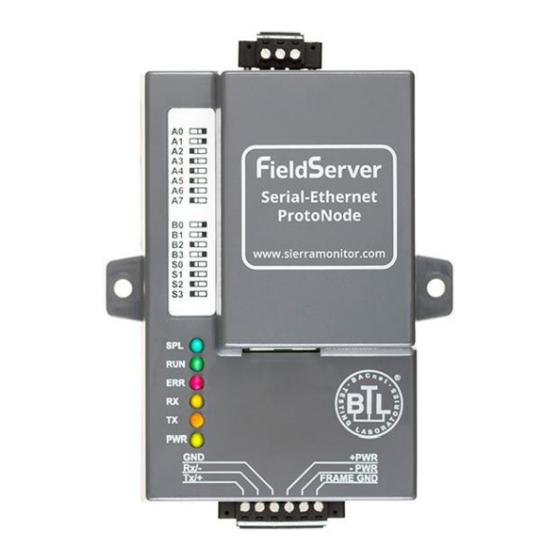
ProtoNode Start-Up Guide INTERFACING PROTONODE TO HOST OEM DEVICE ProtoNode FPC-N34 and FPC-N35 Showing Connection Ports Figure 5: ProtoNode BACnet FPC-N34 (upper) and ProtoNode FPC-N35 (lower) Page 10 of 37... -
Page 11: Device Connections To Protonode
Figure 6: R2 Port Device Connections to ProtoNode ProtoNode 6 Pin Phoenix connector for RS-485 Devices The 6 pin Phoenix connector is the same for ProtoNode FPC-N34 (BACnet) and FPC-N35 (LonWorks). Pins 1 through 3 are for Modbus RS-485 devices. -
Page 12: Resistor And Power Jumper Information
ProtoNode Start-Up Guide Resistor and Power Jumper Information 4.3.1 Bias Resistors Bias Resistors Figure 8: Bias Resistors The ProtoNode bias resistors are used to keep the RS-485 bus to a known state, when there is no transmission on the line (bus is idling), to help prevent false bits of data from being detected. The bias resistors typically pull one line high and the other low - i.e. -
Page 13: 4.3.2 Termination Resistor
ProtoNode Start-Up Guide 4.3.2 Termination Resistor Termination Resistor Figure 9: Termination Resistor Termination resistors are also used to reduce noise. These pull the two lines of an idle bus together. However, they would override the effect of any bias resistors, if connected. Page 13 of 37... -
Page 14: 4.3.3 Power Jumper Settings
ProtoNode Start-Up Guide 4.3.3 Power Jumper Settings Power Jumper Switch in position “A” Figure 10: Power Jumper Switch The ProtoNode Carrier Board power jumper is set to position A by default, but can be changed to position B for other power supply requirements. Position A: The Carrier makes use of a full-wave rectifying bridge. -
Page 15: Wiring Field Port To Rs-485 Bms Network
ProtoNode Start-Up Guide Wiring Field Port to RS-485 BMS Network Connect the RS-485 network wires to the 3-pin RS-485 connector on ProtoNode FPC-N34 as shown below in Figure The RS-485 GND (Pin 3) is not typically connected If the ProtoNode is the last device on the RS-485 trunk, then the End-Of-Line Termination... -
Page 16: Power-Up Protonode
ProtoNode Start-Up Guide Power-Up ProtoNode Apply power to ProtoNode as show below in Figure 15. Ensure that the power supply used complies with the specifications provided in Appendix C.1. ProtoNode accepts either 9-30VDC or 12-24 VAC on pins 4 and 5. ... -
Page 17: Connect The Protonode's Web Gui To Setup Ip Address For Ethernet Network
ProtoNode Start-Up Guide CONNECT THE PROTONODE’S WEB GUI TO SETUP IP ADDRESS FOR ETHERNET NETWORK Connect the PC to ProtoNode via the Ethernet Port Connect a CAT5 Ethernet cable (Straight through or Cross-Over) between the PC and ProtoNode. The Default IP Address of ProtoNode is 192.168.1.24, Subnet Mask is 255.255.255.0. -
Page 18: Setting Ip Address For Field Network
ProtoNode Start-Up Guide Setting IP Address for Field Network After setting a local PC to be on the same subnet as the ProtoNode (Section 5.1), open a web browser on the PC and enter the IP Address of the ProtoNode; the default address is 192.168.1.24. -
Page 19: Figure 19: Changing Ip Address Via Web Gui
ProtoNode Start-Up Guide From the Web GUI’s landing page, click on “Setup” to expand the navigation tree and then select “Network Settings” to access the IP Settings menu. (Figure Figure 17: Changing IP Address via Web GUI Modify the IP Address (N1 IP Address field) of the ProtoNode Ethernet port. ... -
Page 20: Lonworks (Fpc-N35): Commissioning Protonode On A Lonworks Network
ProtoNode Start-Up Guide LONWORKS (FPC-N35): COMMISSIONING PROTONODE ON A LONWORKS NETWORK Commissioning may only be performed by the LonWorks administrator. Commissioning ProtoNode FPC-N35 on a LonW orks Network The User will be prompted by the LonWorks Administrator to hit the Service Pin on the ProtoNode FPC-N35 at the correct step of the Commissioning process which is different for each LonWorks Network Management Tool. -
Page 21: Figure 17: Sample Of Fserver.xif File Being Generated
ProtoNode Start-Up Guide For Windows XP and Windows 7, use the following IP Address: Click twice. Open a web browser and go to the following address: [IP Address of ProtoNode]/fserver.xif Example: 192.168.1.24/fserver.xif If the web browser prompts to save the file, save the file onto the PC. If the web browser displays the xif file as a web page, save the file on the local PC as “fserver.xif”. -
Page 22: Appendix A. Troubleshooting
ProtoNode Start-Up Guide Appendix A. Troubleshooting Appendix A.1. Lost or Incorrect IP Address Ensure that FieldServer Toolbox is Loaded on the PC that is currently being used, or download FieldServer-Toolbox.zip on the Sierra Monitor webpage, under Customer Care: Resource Center, Software Downloads: www.sierramonitor.com/customer-care/resource-center?filters=software-downloads ... -
Page 23: Appendix A.2. Viewing Diagnostic Information
ProtoNode Start-Up Guide Appendix A.2. Viewing Diagnostic information Type the IP Address of the ProtoNode into the local PC’s web browser or use the FieldServer Toolbox to connect to the ProtoNode. Click on Diagnostics and Debugging Button, then click on view, and then on connections. ... -
Page 24: Appendix A.3. Check Wiring And Settings
ProtoNode Start-Up Guide Appendix A.3. Check Wiring and Settings No COMS on Modbus RTU side. If Tx/Rx are not flashing rapidly then there is a COM issue on the Modbus side. To fix this problem, check the following: Visual observations of LEDs on ProtoNode. (Appendix A.4) Check baud rate, parity, data bits, stop bits... -
Page 25: Appendix A.4. Led Diagnostics For Communications Between Protonode And Devices
ProtoNode Start-Up Guide Appendix A.4. LED Diagnostics for Communications Between ProtoNode and Devices Please see the diagram below for ProtoNode FPC-N34 and FPC-N35 LED Locations. Diagnostic LEDs Description The SPL LED will light if the unit is not getting a response from one or more of the configured devices. -
Page 26: Appendix A.5. Take Diagnostic Capture With The Fieldserver Toolbox
ProtoNode Start-Up Guide Appendix A.5. Take Diagnostic Capture With the FieldServer Toolbox Once the Diagnostic Capture is complete, email it to support@sierramonitor.com. The Diagnostic Capture will allow us to rapidly diagnose the problem. Ensure that FieldServer Toolbox is Loaded on the PC that is currently being used, or download FieldServer-Toolbox.zip on the Sierra Monitor Corporation webpage, under Customer Care: Resource Center, Software Downloads: www.sierramonitor.com/customer-care/resource-center?filters=software-downloads... - Page 27 ProtoNode Start-Up Guide Select full Diagnostic NOTE: If desired, the default capture period can be changed. Click on Start Diagnostic Wait for Capture period to finish, then the Diagnostic Test Complete window will appear Page 27 of 37...
- Page 28 ProtoNode Start-Up Guide Step 2: Send Log Once the Diagnostic test is complete, a .zip file will be saved on the PC Choose Open to launch explorer and have it point directly at the correct folder Send the Diagnostic zip file to support@sierramonitor.com Page 28 of 37...
-
Page 29: Appendix A.6. Update Firmware
ProtoNode Start-Up Guide Appendix A.6. Update Firmware To load a new version of the firmware, follow these instructions: 1. Extract and save the new file onto the local PC. 2. Open a web browser and type the IP Address of the FieldServer in the address bar. NOTE: Default IP Address is 192.168.1.24 NOTE: Use the FS Toolbox utility if the IP Address is unknown (Appendix... -
Page 30: Appendix A.8. Passwords
ProtoNode Start-Up Guide Appendix A.8. Passwords Access to the ProtoNode can be restricted by enabling a password. There are 2 access levels defined by 2 account names: Admin and User. The Admin account has unrestricted access to the ProtoNode. ... -
Page 31: Appendix B. Vendor Information
ProtoNode Start-Up Guide Appendix B. Vendor Information Appendix B.1. Additional DIP switch settings When more configuration settings are needed than possible via the external S Bank DIP Switches, then the user can access the A Bank DIP Switches internal to the ProtoNode. NOTE: The lid on top of the ProtoNode has to be removed in order to select the A Bank of DIP switches. -
Page 32: Appendix C. Reference
ProtoNode Start-Up Guide Appendix C. Reference Appendix C.1. Specifications ProtoNode FPC-N35/-N37/-N39 ProtoNode FPC-N34/-N36/-N38 One 6-pin Phoenix connector with: One 6-pin Phoenix connector with: RS-485 port (+ / - / gnd) RS-485 port (+ / - / gnd) Power port (+ / - / Frame-gnd) -
Page 33: Appendix C.1.1. Compliance With Ul Regulations
ProtoNode Start-Up Guide Appendix C.1.1. Compliance with UL Regulations For UL compliance, the following instructions must be met when operating ProtoNode. The units shall be powered by listed LPS or Class 2 power supply suited to the expected operating temperature range. ... -
Page 34: Appendix D. Bank Dip Switch Settings
ProtoNode Start-Up Guide Appendix D. Bank DIP Switch Settings Appendix D.1. “A” Bank DIP Switch Settings Address A0 Address A0 Page 34 of 37... - Page 35 ProtoNode Start-Up Guide Address A0 Address A0 Page 35 of 37...
- Page 36 ProtoNode Start-Up Guide Address A0 Address A0 Page 36 of 37...
-
Page 37: Appendix E. Limited 2 Year Warranty
ProtoNode Start-Up Guide Appendix E. Limited 2 Year Warranty Sierra Monitor Corporation warrants its products to be free from defects in workmanship or material under normal use and service for two years after date of shipment. Sierra Monitor Corporation will repair or replace any equipment found to be defective during the warranty period.
Need help?
Do you have a question about the FPC-N34 and is the answer not in the manual?
Questions and answers