
Related Manuals for National Instruments QuickSyn FSW-0010, QuickSyn FSW-0020


Summary of Contents for National Instruments QuickSyn FSW-0010, QuickSyn FSW-0020
- Page 1 QuickSyn QuickSyn ® ® MICROWAVE FREQUENCY SYNTHESIZER MICROWAVE FREQUENCY SYNTHESIZER User Guide User Guide DOC. NO. 5580513-01 | REV. F | ECN 001779 National Instruments | 4600 Patrick Henry Drive, Santa Clara CA 95054 | 408-610-6810 | ni-microwavecomponents.com...
- Page 2 National Instruments Software Copyright or an authorized service facility. In-warranty units will be returned Original National Instruments WARNING freight prepaid;...
-
Page 3: Table Of Contents
User Guide Introducing the QuickSyn Frequency Synthesizer Congratulations on purchasing a QuickSyn Frequency Synthesizer! To get the most out of your purchase, it is recommended that this be read carefully and completely. User Guide In this document . . . The scope of this document is to describe how to setup the QuickSyn Frequency Synthesizer, install its software on a computer, and control the Synthesizer using the software. -
Page 4: Step 1. Unpack Hardware
User Guide Step 1. Unpack Hardware Inspect shipping cartons for any sign of visible or concealed damage. If cartons are damaged, notify the carrier immediately. The QuickSyn Frequency Synthesizer ships in an antistatic package to prevent CAUTION damage from electrostatic discharge (ESD). Because ESD can damage the components of a hardware unit, store the unit an antistatic bag when not in use. - Page 5 User Guide Figure 1 Example of the QuickSyn USB Device Driver Installer A window similar to the one shown in Figure 1 will appear. Figure 2 Example of End User License Agreement Select Next to continue to the End User License Agreement. Carefully read through the End User License Agreement.
- Page 6 User Guide Figure 3 Example of “Installing USB Driver” progress of various software components being installed. Figure 4 Example of “Windows Logo Testing” Select Next once the files have been copied. The QuickSyn device driver uses files that already exist on the computer as part NOTE of a standard Windows installation and does not install EXE, DLL, or any other executable files.
- Page 7 User Guide Figure 5 Example of Completing USB Device Driver Installer Select Continue Anyway. Select Finish to complete the USB device driver installation. Connect the QuickSyn Synthesizer to the PC using a USB Cable and proceed to Step 3. A quick-start kit containing all the necessary cables and a power supply to quickly NOTE setup and run the QuickSyn Synthesizer is available for order as MFSW-ACC06.
- Page 8 User Guide Figure 6 Example of the “Found New Hardware Wizard” Select “No, not this time” and Next to continue. Figure 7 Example of “What Do You Want the Wizard to Do” Select “Install from a list or specific location (Advanced)” and Next to continue.
- Page 9 User Guide Figure 8 Example of “choose search and installation options” Select “Search for the best driver in these locations.” Check the box to “Include this location in the Search” and enter the file path in the combo-box or select Browse and search for the device driver file (QuickSyn.inf) that was downloaded in step 1.
- Page 10 User Guide Figure 10 Example of “Windows Logo Testing” Select “Continue Anyway” The QuickSyn device driver uses files that already exist on the computer as part ® NOTE of a standard Windows installation and does not install EXE, DLL, or any other executable files.
- Page 11 User Guide Step 2-3 Install Device Driver Using Manual Installation (Windows 7) Download the latest available QuickSyn device driver from the NI Microwave Components website (ni-microwavecomponents. com). Connect the QuickSyn Synthesizer to the PC using a USB cable. A quick-start kit containing all the necessary cables and a power supply to quickly NOTE setup and run the QuickSyn Synthesizer is available for order as MFSW-ACC06.
- Page 12 User Guide Click on the Windows logo in the lower-left corner of the screen, and select Drivers and Printers as shown in Figure 15. Figure 15 Example of How to Start Manual Installation of Driver Figure 16 Example of Finding a Device Find the device labeled “FSW_USBSerial”...
- Page 13 User Guide Figure 17 Example of FSW_USBSerial Properties Click on the Hardware tab (see figure 17). QuickSyn Frequency Synthesizer 13 of 44...
- Page 14 User Guide Figure 18 Example of FSW_USBSerial Properties Select the Properties button to display the properties dialog box (see Figure 18). 14 of 44 QuickSyn Frequency Synthesizer...
- Page 15 User Guide Figure 19 Example of FSW_USBSerial Properties Select Change settings (see Figure 19) to enable the Update Driver button and click on the Update Driver button. Figure 20 Example of Update Driver Software Select the browse option as shown in Figure 20. QuickSyn Frequency Synthesizer 15 of 44...
- Page 16 User Guide Figure 21 Example of Update Driver Software Figure 22 Example of Browse for Folder 10 Browse to the location of the location of the QuickSyn.inf. file and choose Ok (see Figure 22). 16 of 44 QuickSyn Frequency Synthesizer...
- Page 17 User Guide Figure 23 Example of Update Driver Software 11 Click Next to begin installing the driver (see Figure 23). A Windows security dialog box will pop up asking to approve the installation. The driver has been signed by NI Microwave Components (formerly Phase Matrix, Inc.).
- Page 18 User Guide Figure 25 Example of Windows Security Message In the Control Panel under Devices and Printers, the QuickSyn USB interface should now be listed along with its com port number as shown in Figure 26. Keep the com port number handy as it will be needed in order to communicate with the QuickSyn Synthesizer.
-
Page 19: Step 3. Perform Software Installation
User Guide Step 3. Perform Software Installation 1 Download the latest available QuickSyn Soft Front Panel software from the NI Microwave Components website and unzip it to a location on the computer. Software is available online at ni-microwavecomponents.com 2 Start the installation process by selecting Start > Run > Browse, navigate to the “setup.exe”... - Page 20 User Guide Figure 28 Example of Selecting Destination Directory for Executables 4 Enter the destination directory for the Soft Front Panel executables or browse to a destination directory by selecting the Browse button. 5 Once the file path has been entered, select Next to continue to the Software License Agreement.
- Page 21 User Guide 6 Carefully read through the Software License Agreement. • If you agree to the terms of the software license agreement, select “I accept the License Agreement” and select Next to continue. • If you do not agree, you will not be able to install the software. 7 Select Finish to complete the Soft Front Panel installation.
-
Page 22: Step 4. Setup Synthesizer
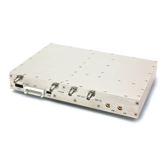
User Guide Step 4. Setup Synthesizer A quick-start kit that contains all the necessary cables and a power supply to quickly NOTE setup and run the QuickSyn Synthesizer is available for order as MFSW-ACC06. 1 Insert one end of an SMA cable to the Synthesizer’s RF OUT SMA connector and the other end of the cable to the applicable microwave test equipment as shown in Figure 32. - Page 23 User Guide Figure 32 Connection diagram QuickSyn Frequency Synthesizer 23 of 44...
-
Page 24: Step 5. Review Software Front Panels
User Guide Step 5. Review Software Front Panels Step 5-1 Launch QuickSyn Soft Front Panel Software 1 Use the shortcut icon that was placed on the computer’s desktop during installation to launch the QuickSyn Soft Front Panel software. The “Locate QuickSyn Device” dialog box will appear (see Figure 33). Figure 33 Example of “Locate QuickSyn Device”... - Page 25 User Guide Step 5-2 Review the Main Control Panel The QuickSyn Synthesizer Soft Front Panel is a graphical user interface (GUI) that provides a quick and easy way to exercise the Synthesizer’s extensive functionality (see Figure 34). The GUI contains three tabs in the upper-left corner. These tabs represent the three logical groups of functionality—main control, sweep mode, and list mode.
- Page 26 User Guide Model Number, Serial Number, Calibration Date, Options, Firmware Ver The information area, located in the upper-right corner of the Main Control panel, reveals the Synthesizer’s model number, serial number, date of last calibration, currently installed options, and firmware version. This information cannot be changed with the Soft Front Panel.
- Page 27 User Guide Synthesizer Frequency This rotary control (along with an entry box) is used to select a fixed frequency. A frequency value may be selected by pointing the rotary control and dragging it around to the left or right until the desired frequency is reached. The LOCKED indicator will illuminate when the Synthesizer settles on the target frequency.
- Page 28 User Guide internal “pull-up” resistor to keep power on when there is nothing connected to the Pulse input connector. To maximize the pulse- modulation on-off ratio, set the Synthesizer’s output power from the Main Control panel to maximum power. By default pulse modulation is off.
- Page 29 User Guide Reference, Frequency, Power, Temperature These settings and status indicators (see Figure 35) located toward the bottom of the Main Control panel provide an easily visible indication of the currently selected reference type, frequency, and power. In addition, the internal temperature of the Synthesizer is displayed. The values in these indicators will update as settings and temperature change.
- Page 30 User Guide Table 1 Factory Default Settings Setting Default Value RF Output Frequency 10 GHz Output Power +15 dBm (FSW-0010) +13 dBm (FSW-0020) Blanking Reference Source Internal Reference Output Pulse Modulation Amplitude Modulation AM Sensitivity Frequency Modulation FM Sensitivity QuickSyn Frequency Synthesizer 30 of 44...
- Page 31 User Guide Step 5-3 Review the Sweep Mode Panel The Sweep Mode panel, as shown in Figure 37, is accessible by selecting the Sweep Mode tab located in the upper-left corner of the Main Control panel. The Sweep Mode panel allows the user to set triggering, sweep direction, frequency range and step size, power range and step size, and frequency and power dwell time.
- Page 32 User Guide Dwell Time (usec) The Dwell Time entry box is used to enter the dwell time, which is the time that each point (frequency or power) in the sweep will remain static before moving to the next point. The dwell time is not used when Enable List Point Trigger is selected.
- Page 33 User Guide Sweep Mode The buttons in the Frequency Sweep Settings area of the Sweep Mode panel allow the user to set the parameters necessary for frequency sweeps. • When Normal Mode is selected, the Start Freq, Stop Freq, Power, and Step Freq entry boxes are available for the user to enter values.
- Page 34 User Guide Stop Sweep The red Stop Sweep button under the Frequency Sweep Settings area of the Sweep Mode panel is used to halt frequency sweeps. Sweep Mode The buttons in the Power Sweep Settings area of the Sweep Mode panel allow the user to set the parameters necessary for power sweeps.
- Page 35 User Guide Start Sweep The Start Sweep button under the Power Sweep Settings area of the Sweep Mode panel is used to execute power sweeps after parameters are set. Stop Sweep The red Stop Sweep button under the Power Sweep Settings area of the Sweep Mode panel is used to halt power sweeps.
- Page 36 User Guide Set Trigger The buttons in the Set Trigger area of the List Mode panel allow the user to select trigger mode. • When No Trigger is selected and the Run List button is pressed, sweeps begin immediately upon execution. •...
- Page 37 User Guide Number of Sweeps This entry box is used to define the number of times a sweep is executed. To enter a number of sweeps, highlight the entry box and enter the desired value. The up/down arrow on the left side of the entry box can be used to increase or decrease the value.
- Page 38 User Guide Step 5-5 Review the Edit List Dialog Box The Edit List dialog box, shown in Figure 39, is accessible by selecting the Create/Edit List button on the List Mode panel. Figure 39 Edit List Dialog Box Point Number, Frequency, Power and Dwell Time These entry boxes enable the user to specify point number, frequency, power, and dwell time values for creating sweep lists.
- Page 39 User Guide Create New List When the Create New List button is selected, the Create List dialog box (see Figure 41) appears. Get List From File This button is used to locate and retrieve a previously defined and saved list. Selecting the Get List From File button launches a browsing window that will enable the user to find the file.
- Page 40 User Guide Step 5-6 Review the Create List Dialog Box The Create List dialog box, shown in Figure 41, is accessible by selecting the Create New List button in the Edit List dialog box. The entry boxes on the Edit List dialog box are automatically populated when the entry boxes within the Create List dialog box are filled and the Create List button is selected.
- Page 41 User Guide Create List Selecting the Create List button executes the action of populating the entry boxes in the Edit List dialog box. Cancel The Cancel button in the Create List dialog box, closes the dialog box and does not save the values entered in the entry boxes. QuickSyn Frequency Synthesizer 41 of 44...
-
Page 42: Service Information
User Guide Service Information Periodic Maintenance There are no hardware adjustments within QuickSyn Synthesizers. NI Microwave Components recommends that the QuickSyn Synthesizer is calibrated every 24 months or whenever a problem is suspected. The specific calibration interval depends upon the accuracy required. - Page 43 User Guide Factory Service If you are returning a QuickSyn Synthesizer for service or repair, be sure to include the following information with the shipment: • Name and address of owner • Model, complete serial number, options, and firmware version. •...
- Page 44 User Guide DECLARATION OF CONFORMITY Manufacturer’s Name: Phase Matrix, Inc. Manufacturer’s Address: 4600 Patrick Henry Drive Santa Clara CA 95054 Product Name: QuickSyn® Synthesizer Model Number: FSW-0010, FSW-0020 Statement: Phase Matrix, Inc. declares that the aforementioned product(s) conform(s) to the following Council Directives of the European Union: Rohs Directive 2011/65/EU Low Voltage Directive 2006/95/EC...
Need help?
Do you have a question about the QuickSyn FSW-0010, QuickSyn FSW-0020 and is the answer not in the manual?
Questions and answers