Table of Contents
Advertisement
Advertisement
Table of Contents

Related Manuals for thomann Stairville Show Bar Pro 16x10W RGBAW IP65


Summary of Contents for thomann Stairville Show Bar Pro 16x10W RGBAW IP65
- Page 1 Show Bar Pro 16x10W RGBAW IP65 LED floodlight user manual...
- Page 2 Musikhaus Thomann Thomann GmbH Hans-Thomann-Straße 1 96138 Burgebrach Germany Telephone: +49 (0) 9546 9223-0 E-mail: info@thomann.de Internet: www.thomann.de 06.08.2018, ID: 347910 (V2)
-
Page 3: Table Of Contents
Table of contents Table of contents General notes............................... 5 1.1 Further information........................... 6 1.2 Notational conventions........................7 1.3 Symbols and signal words....................... 7 Safety instructions..........................10 Features............................... 15 Installation..............................17 Starting up..............................21 Connections and controls........................24 Operating..............................27 7.1 Starting the device........................... 27 7.2 Main menu............................ - Page 4 Table of contents 7.6 Functions in 9-channel DMX mode................... 39 7.7 Functions in 80-channel DMX mode..................44 Technical specifications........................48 Plug and connection assignments....................50 Troubleshooting............................51 Cleaning............................... 53 Protecting the environment......................54 LED floodlight...
-
Page 5: General Notes
General notes General notes This manual contains important instructions for the safe operation of the unit. Read and follow the safety instructions and all other instructions. Keep the manual for future reference. Make sure that it is available to all those using the device. If you sell the unit please make sure that the buyer also receives this manual. -
Page 6: Further Information
General notes 1.1 Further information On our website (www.thomann.de) you will find lots of further information and details on the following points: Download This manual is also available as PDF file for you to download. Use the search function in the electronic version to find the topics of Keyword search interest for you quickly. -
Page 7: Notational Conventions
General notes 1.2 Notational conventions This manual uses the following notational conventions: Letterings The letterings for connectors and controls are marked by square brackets and italics. Examples: [VOLUME] control, [Mono] button. Displays Texts and values displayed on the device are marked by quotation marks and italics. Examples: ‘24ch’... - Page 8 General notes Signal word Meaning DANGER! This combination of symbol and signal word indicates an immediate dangerous situation that will result in death or serious injury if it is not avoided. WARNING! This combination of symbol and signal word indicates a pos‐ sible dangerous situation that can result in death or serious injury if it is not avoided.
- Page 9 General notes Warning signs Type of danger Warning – suspended load. Warning – danger zone. Show Bar Pro 16x10W RGBAW IP65...
-
Page 10: Safety Instructions
Safety instructions Safety instructions Intended use This device is intended for use as an electronic lighting effect by means of LED technology. The device is designed for professional use and is not suitable for use in households. Use the device only as described in this user manual. Any other use or use under other operating con‐ ditions is considered to be improper and may result in personal injury or property damage. - Page 11 Safety instructions Safety DANGER! Danger for children Ensure that plastic bags, packaging, etc. are disposed of properly and are not within reach of babies and young children. Choking hazard! Ensure that children do not detach any small parts (e.g. knobs or the like) from the unit.
- Page 12 Safety instructions DANGER! Electric shock caused by high voltages inside Within the device there are areas where high voltages may be present. Never remove any covers. There are no user-serviceable parts inside. Do not use the device if covers, protectors or optical components are missing or damaged.
- Page 13 Safety instructions WARNING! Risk of epileptic shock Strobe lighting can trigger seizures in photosensitive epilepsy. Sensitive persons should avoid looking at strobe lights. WARNING! Risk of burns The surface of the device can become very hot during operation. Do not touch the device with bare hands during operation, and after switching off wait for at least 15 minutes.
- Page 14 Safety instructions NOTICE! Power supply Before connecting the device, ensure that the input voltage (AC outlet) matches the voltage rating of the device and that the AC outlet is protected by a residual current circuit breaker. Failure to do so could result in damage to the device and possibly injure the user.
-
Page 15: Features
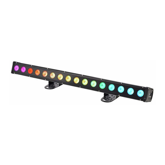
Features Features The LED floodlight is particularly suited for professional lighting tasks in tour and festival use. 16 5-in-1 RGBAW LEDs (10 W each) special positioning of the LEDs for superior colour mixing already over short distances also suited for fixed installation due to extensive control options Operating modes –... - Page 16 Features Information about protection Equipment with protection class IP65 are dust-tight and completely protected against contact class IP65 (first code number). They are also protected against splash water from any angle (second code digit). That is why this equipment can also be used outdoors. Event technology equipment is generally only designed for temporary use however (event lighting) and not for permanent use outdoors.
-
Page 17: Installation
Installation Installation Unpack and carefully check that there is no transportation damage before using the unit. Keep the equipment packaging. To fully protect the device against vibration, dust and moisture during transportation or storage use the original packaging or your own packaging material suitable for transport or storage, respectively. - Page 18 Installation NOTICE! Risk of overheating Always ensure sufficient ventilation. The ambient temperature must not exceed the limits stated in the chapter Tech‐ nical Specifications of the User Manual. NOTICE! Use of stands When mounting the device onto a stand, ensure that the stand is in a safe and stable position and that the weight of the device does not exceed the maximum permissible load capacity of the stand.
- Page 19 Moisture entering into open connectors (plugs and couplers) of DMX or power cords can cause short circuits. Close unused connectors with end caps intended for this purpose (www.thomann.de). Mounting options You can install the device on the wall, the ceiling or on the ground. Two mounting brackets and the necessary screws are included.
- Page 20 Installation Always work from a stable platform whenever installing, moving or servicing the unit. In doing so, the area underneath the unit must be cordoned off. Attaching the filter The filter, optionally available as accessory (item no. 437012), can be fixed at the front of the unit with four undetachable thumb screws.
-
Page 21: Starting Up
Starting up Starting up Create all connections while the device is off. Use the shortest possible high-quality cables for all connections. Take care when running the cables to prevent tripping hazards. Show Bar Pro 16x10W RGBAW IP65... - Page 22 Starting up Connections in ‘DMX’ mode Connect the DMX input of the device to the DMX output of a DMX controller or other DMX device. Connect the output of the first DMX device to the input of the second one and so on, to form a series connection.
- Page 23 Starting up DMX indicator If the unit is in DMX mode and a DMX controller is connected and turned on, the ‘d’ is flashing in the first digit of the display. Connections in ‘Master / When you configure a group of devices in ‘Master / Slave’ mode, the first device controls the Slave‘...
-
Page 24: Connections And Controls
Connections and controls Connections and controls LED floodlight... - Page 25 Connections and controls 1 [Power In] Lockable input socket (Power Twist IP65 True 1) for power supply 2 [DMX In] DMX input. 3 Horizontally slidable mounting bracket which is adjustable in inclination 4 Locking screws for locking the floodlight in the desired orientation 5 [DMX Out] DMX output 6 [Power Out]...
- Page 26 Connections and controls Control panel and display 9 Display. 10 [MODE] Activates the main menu or toggles between menu items. 11 [SETUP] Chooses between the options of the selected mode 12 [UP] Navigates upwards in a menu list. Increases the displayed value by one. 13 Taste [DOWN] Navigates downwards in a menu list.
-
Page 27: Operating
Operating Operating 7.1 Starting the device Connect the device to the power supply to start operation. After a few seconds, the display indicates that a reset is in progress. The device is then ready for use. The display shows the operating mode that was selected when the unit was last powered off. - Page 28 Operating Operating mode ‘Automatic’ Automatic operation can only be activated when the unit is operating in stand alone mode or as master in a master / slave combination. This setting is only relevant if the device is not con‐ trolled via DMX. Press [MODE] repeatedly until the display shows ‘AUTO’...
- Page 29 Operating Operating mode ‘Preprog‐ A preprogrammed automatic show can only be activated when the unit is operating in stand- rammed automatic show’ alone mode or as master in a master / slave combination. This setting is only relevant if the device is not controlled via DMX.
- Page 30 Operating Operating mode ‘Slave’ This setting is only relevant if the device is serving as Slave in a Master / Slave configuration and is not controlled via DMX. Press [MODE] repeatedly until the display shows ‘SLAv’ and confirm with [SETUP]. LED floodlight...
- Page 31 Operating DMX mode This setting is only relevant when the device is controlled via DMX. Press [MODE] repeatedly until the display shows ‘d.xxx’ . Press [SETUP]. Now you can set the number of the first DMX channel to be used by the device (DMX address). Use [UP] and [DOWN] to select a value between 1 and 512 (display shows ‘d.001’...
- Page 32 Operating ‘80-CH’ (eighty channels) LED floodlight...
- Page 33 Operating Constant unicoloured pattern A constant unicoloured pattern can only be activated when the unit is operating in stand alone mode or as master in a master / slave combination. This setting is only relevant if the device is not controlled via DMX. Press [MODE] repeatedly until the display shows ‘CoLr’...
- Page 34 Operating Dimmer curve Press [MODE] repeatedly until the display shows ‘Set’ . Press [SETUP]. Use [UP] | [DOWN] to select the menu item ‘CuSE’ and confirm with [SETUP]. Use [UP] | [DOWN] to select one of the following dimmer curves. The dimmer curve determines how the brightness increases or decreases depending on the set DMX value.
- Page 35 Operating Reset Press [MODE] repeatedly until the display shows ‘Set’ . [SETUP]. Use [UP] | [DOWN] to select the menu item ‘-rSt’ and confirm with [SETUP]. Use [UP] | [DOWN] to select between ‘-Yes’ (carry out reset) and ‘-NO’ (no reset) and confirm with [SETUP]. Firmware version Press [MODE] repeatedly until the display shows ‘InFo’...
- Page 36 Operating Device temperature Press [MODE] repeatedly until the display shows ‘InFo’ . Press [SETUP]. Use [UP] | [DOWN] to select the menu item ‘Temp’ and confirm with [SETUP]. The display shows ‘t-ok’ when the device termperature is within the permissible range and shows ‘t-NG’ when the device is over‐ heated.
-
Page 37: Menu Overview
Operating 7.3 Menu overview Show Bar Pro 16x10W RGBAW IP65... -
Page 38: Functions In 5-Channel Dmx Mode
Operating 7.4 Functions in 5-channel DMX mode Channel Value Function 0…255 Intensity red (0 % to 100 %), for all LEDs together 0…255 Intensity green (0 % to 100 %), for all LEDs together 0…255 Intensity blue (0 % to 100 %), for all LEDs together 0…255 Intensity white (0 % to 100 %), for all LEDs 0…255... -
Page 39: Functions In 9-Channel Dmx Mode
Operating Channel Value Function 0…255 Intensity green (0 % to 100 %), for all LEDs together 0…255 Intensity blue (0 % to 100 %), for all LEDs together 0…255 Intensity white (0 % to 100 %), for all LEDs 0…255 Intensity amber (0 % to 100 %), for all LEDs Strobe effect 0…255... - Page 40 Operating Channel Value Function 0…255 Intensity green (0 % to 100 %) 0…255 Intensity blue (0 % to 100 %) 0…255 Intensity white (0 % to 100 %) 0…255 Intensity amber (0 % to 100 %), for all LEDs No function 1…9 Preprogrammed automatic show no.
- Page 41 Operating Channel Value Function 80…89 Preprogrammed automatic show no. 09 90…99 Preprogrammed automatic show no. 10 100…109 Preprogrammed automatic show no. 11 110…119 Preprogrammed automatic show no. 12 120…129 Preprogrammed automatic show no. 13 130…139 Preprogrammed automatic show no. 14 140…149 Preprogrammed automatic show no.
- Page 42 Operating Channel Value Function 210…219 Preprogrammed automatic show no. 22 220…229 Preprogrammed automatic show no. 23 230…239 Preprogrammed automatic show no. 24 240…255 Preprogrammed automatic show no. 25 Function depending on setting of channel 7 Channel 7 = 1…9 0…12 Blackout (R: 0;...
- Page 43 Operating Channel Value Function 91…103 R: 255; G: 255; B: 0; W: 0; A: 255 104…116 R: 255; G: 0; B: 255; W: 0; A: 0 117…129 R: 255; G: 0; B: 120; W: 0; A: 0 130…142 R: 0; G: 255; B: 255; W: 0; A: 0 143…155 R: 255;...
-
Page 44: Functions In 80-Channel Dmx Mode
Operating Channel Value Function Channel 7 = 10…255 0…255 Programme speed Pr.02…Pr.25 Strobe effect 0…255 Stroboscope effect (0 % to 100 %) 7.7 Functions in 80-channel DMX mode In this mode, the intensitiy of each colour of each LED can be controlled separately. The fol‐ lowing table shows the assignment of the DMX channels. - Page 45 Operating Red, LED 2 Green, LED 2 Blue, LED 2 White, LED 2 Amber, LED 2 Channel 11 Channel 12 Channel 13 Channel 14 Channel 15 Red, LED 3 Green, LED 3 Blue, LED 3 White, LED 3 Amber, LED 3 Channel 16 Channel 17 Channel 18...
- Page 46 Operating Red, LED 9 Green, LED 9 Blue, LED 9 White, LED 9 Amber, LED 9 Channel 46 Channel 47 Channel 48 Channel 49 Channel 50 Red, LED 10 Green, LED 10 Blue, LED 10 White, LED 10 Amber, LED 10 Channel 51 Channel 52 Channel 53...
- Page 47 Operating Channel 76 Channel 77 Channel 78 Channel 79 Channel 80 Red, LED 16 Green, LED 16 Blue, LED 16 White, LED 16 Amber, LED 16 Show Bar Pro 16x10W RGBAW IP65...
-
Page 48: Technical Specifications
Technical specifications Technical specifications LEDs 16 5-in-1 RGBAW LEDs (10 W each) Beam angle 20° Number of DMX channels 3, 6 or 72, depending on operating mode Operating supply voltage AC 100 – 240 V 50/60 Hz Power consumption 190 W Protection IP65 Dimensions (W ×... - Page 49 Technical specifications Environmental conditions Temperature range 0 °C…40 °C Relative humidity 50 %, non-condensing Show Bar Pro 16x10W RGBAW IP65...
-
Page 50: Plug And Connection Assignments
Plug and connection assignments Plug and connection assignments Introduction This chapter will help you select the right cables and plugs to connect your valuable equip‐ ment so that a perfect light experience is guaranteed. Please take our tips, because especially in ‘Sound & Light’ caution is indicated: Even if a plug fits into a socket, the result of an incorrect connection may be a destroyed DMX controller, a short circuit or ‘just’... -
Page 51: Troubleshooting
Troubleshooting Troubleshooting NOTICE! Possible data transmission errors For error-free operation make use of dedicated DMX cables and do not use ordi‐ nary microphone cables. Never connect the DMX input or output to audio devices such as mixers or ampli‐ fiers. In the following we list a few common problems that may occur during operation. - Page 52 4. Check to see if the DMX cables run near or alongside to high voltage cables that may cause damage or inter‐ ference to DMX interface circuits. If the procedures recommended above do not succeed, please contact our Service Center. You can find the contact information at www.thomann.de. LED floodlight...
-
Page 53: Cleaning
Cleaning Cleaning Optical lenses Clean the optical lenses, that are accessible from the outside, regularly in order to optimize the light output. The frequency of cleaning depends on the operating environment: wet, smoky or particularly dirty surroundings can cause more accumulation of dirt on the optics of the device. -
Page 54: Protecting The Environment
Protecting the environment Protecting the environment Disposal of the packaging mate‐ rial For the transport and protective packaging, environmentally friendly materials have been chosen that can be supplied to normal recycling. Ensure that plastic bags, packaging, etc. are properly disposed of. Do not just dispose these materials with your normal household waste, but make sure that they are fed to a recovery. - Page 55 Protecting the environment Disposal of your old device This product is subject to the European Waste Electrical and Electronic Equipment Directive (WEEE) in its currently valid version. Do not dispose with your normal household waste. Dispose this device through an approved waste disposal firm or through your local waste facility.
- Page 56 Notes LED floodlight...
- Page 57 Notes Show Bar Pro 16x10W RGBAW IP65...
- Page 58 Notes LED floodlight...
- Page 60 Musikhaus Thomann · Hans-Thomann-Straße 1 · 96138 Burgebrach · Germany · www.thomann.de...
Need help?
Do you have a question about the Stairville Show Bar Pro 16x10W RGBAW IP65 and is the answer not in the manual?
Questions and answers