
Related Manuals for Transition Networks SDSTX3110-121S-LRT

Summary of Contents for Transition Networks SDSTX3110-121S-LRT
- Page 1 Transition Networks SDSTX3110-121S-LRT User Guide SDSTX3110-121S-LRT Industrial Serial Device Server User Guide 33745 Rev. A 33745 Rev. A https://www.transition.com Page 1 of 109...
-
Page 2: Record Of Revisions
Copyright Restrictions © 2018 Transition Networks, Inc. All rights reserved. No part of this work may be reproduced or used in any form or by any means (graphic, electronic, or mechanical) without written permission from Transition Networks. SDSTX3110-121S-LRT Industrial Serial Device Server User Guide, 33745 Rev. A... -
Page 3: Table Of Contents
1.2.2 Software Features ........................6 1.3 Applications ............................7 1.4 Dimensions ............................8 1.4.1 SDSTX3110-121S-LRT Dimensions ....................8 1.5 Pin Definitions ............................ 9 1.5.1 DB9 Connector ..........................9 1.5.2 DB9 Console Port Wiring ......................9 1.5.3 10/100 Base-T(X) MDI/MDI-X Pin Assignments ................ 10 1.6 Package Contents... - Page 4 Transition Networks SDSTX3110-121S-LRT User Guide 4.2 Service Mode ........................... 39 4.2.1 Virtual COM Mode ........................39 4.2.2 TCP Server Mode ........................41 4.2.3 TCP Client Mode ........................43 4.2.4 UDP Mode ..........................44 4.2.5 VCOM List ..........................45 4.2.6 Setup Wizard ..........................46 4.2.8 IP Collection ..........................
-
Page 5: Introduction
COM port on a server, or can be used in pairs to provide serial tunneling across the Ethernet network. The SDSTX3110-121S-LRT is a hardened device designed to operate in the harshest environments. It has a slim IP-30 enclosure that can fit into space-constraining cabinets. The device accepts 12-48VDC power input and it is also certified to operate in temperatures of -40°C to +70°C. -
Page 6: Features
Transition Networks SDSTX3110-121S-LRT User Guide 1.2 Features • Operating Modes: Virtual Com, Serial Tunnel, TCP Server, TCP Client, UDP • Redundant multiple host devices: o 5 host devices: Virtual COM, TCP Server, TCP Client mode; o 4 IP ranges in UDP mode •... -
Page 7: Applications
Transition Networks SDSTX3110-121S-LRT User Guide 1.3 Applications The figure below shows typical SDS configurations (e.g., Multiple Host PCs, SSL Data Encryption, TCP Client/Server Modes, and NAT Router Pass-through). 33745 Rev. A https://www.transition.com Page 7 of 109... -
Page 8: Dimensions
Transition Networks SDSTX3110-121S-LRT User Guide 1.4 Dimensions 1.4.1 SDSTX3110-121S-LRT Dimensions The SDSTX3110-121S-LRT cabinet dimensions are provided below: 33745 Rev. A https://www.transition.com Page 8 of 109... -
Page 9: Pin Definitions
SDSTX3110-121S-LRT User Guide 1.5 Pin Definitions 1.5.1 DB9 Connector The SDSTX3110-121S-LRT serial port can be connected using a DB9 cable. The DB9 connector supports RS232 / RS422 / RS485 operation modes. The table below provides the DB9 connector pin assignments. Pin #... -
Page 10: 10/100 Base-T(X) Mdi/Mdi-X Pin Assignments
Transition Networks SDSTX3110-121S-LRT User Guide 1.5.3 10/100 Base-T(X) MDI/MDI-X Pin Assignments Note: “+” and “-” signs represent the polarity of the wires that make up each wire pair. Pin Number MDI port MDI-X port TD+(transmit) RD+(receive) TD-(transmit) RD-(receive) RD+(receive) TD+(transmit) -
Page 11: Package Contents
Transition Networks SDSTX3110-121S-LRT User Guide 1.6 Package Contents Carefully unpack the items near the final location. Save the packing materials for possible future use. Verify that you received the items below. Contact your sales representative if you have not received all of the... -
Page 12: Hardware Overview
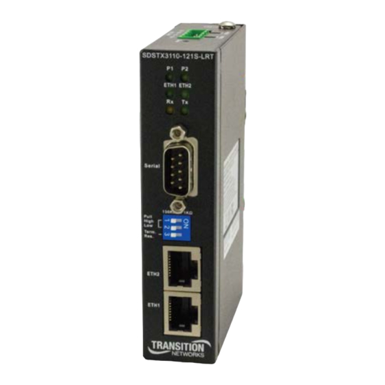
Transition Networks SDSTX3110-121S-LRT User Guide 2. Hardware Overview 2.1 Front Panel SDSTX3110-121S-LRT Front Panel 2.1.1 Ports and Connectors The Ethernet ports on the device use RJ45 connectors. Port Description ETH1 and ETH2 Two 10/100 Base-T(X) ports (ETH 10/100M). Serial Port One DB9 Serial Port. -
Page 13: Dip Switch For Rs 422/485 Termination
Transition Networks SDSTX3110-121S-LRT User Guide 2.1.6 DIP Switch for RS 422/485 Termination Termination is used to match the impedance of a transmission line to the hardware impedance of the interface it is connected to. There is more than one way to add termination to an RS485/422 serial connection. The most commonly used is DC Termination, accomplished by attaching a resistor between the signal lines on the extreme ends of the transmission line. -
Page 14: Top Panel
Transition Networks SDSTX3110-121S-LRT User Guide 2.2 Top Panel The top panel components are shown and described below: 1 Terminal block: V1-, V1+, V2- and V2+ for power connections. 2 Grounding screw (see section 3.4.1 Grounding on page 18). 3 Reset button. -
Page 15: Hardware Installation
A DIN-Rail kit is pre-installed to let you fasten the device to a DIN rail. The dimensions are provided below. SDSTX3110-121S-LRT Dimensions (in mm) 1. Slant the device and screw the DIN-Rail Kit onto the back of the device, right in the middle of the back panel. -
Page 16: Wall Mounting
Transition Networks SDSTX3110-121S-LRT User Guide 3.2 Wall Mounting The SDS can be fixed to the wall via the wall mount kit included in the package. The wall mount kit dimensions are provided below. To install the device on a panel or wall: 1. -
Page 17: Rack Mounting
Transition Networks SDSTX3110-121S-LRT User Guide 3.3 Rack Mounting The SDS can be rack mounted using the procedure below. 1. Install the provided L-shaped mounting brackets to the left and right sides of the device as shown below. 2. With the front brackets oriented in the front of the rack, mount the device in the rack with the four rack- mounting screws. -
Page 18: Wiring
Transition Networks SDSTX3110-121S-LRT User Guide 3.4 Wiring Warning: Do not disconnect modules or wires unless power has been switched off or the area is known to be non-hazardous. The devices may only be connected to the supply voltage shown on the type plate. -
Page 19: Connection
Transition Networks SDSTX3110-121S-LRT User Guide 3.5 Connection 3.5.1 10/100BASE-T(X) Pin Assignments Depending on the link type, the device can use CAT 3, 4, 5, or 5e UTP cables to connect to any other network devices (PCs, servers, switches, routers, or hubs). See the table below for cable specifications. -
Page 20: Management
Two versions of SDS Manager are available; one each to support to support 32-bit and 64-bit Windows systems. 1. Determine which version you require. 2. Download it from the Transition Networks website: SDS Management Software zip file (e.g., filename SDS-Manager_x64_v1.5a_20170413.zip). - Page 21 Transition Networks SDSTX3110-121S-LRT User Guide . Check either the Launch SDS-Manager Now checkbox or the Launch SDS-Manager Later checkbox. When you launch SDS-Manager, a confirmation message displays. 5. Click Yes to restart your computer to complete the installation, or select No and restart it later.
-
Page 22: Sds-Manager Overview
Transition Networks SDSTX3110-121S-LRT User Guide 4.1.2 SDS-Manager Overview SDS-Manager is an easy-to-use Windows utility for managing one or many Serial Device Servers. A Serial Device Server provides a transparent serial gateway to Ethernet without modifying existing COM port control programs. -
Page 23: Using Sds-Manager
Transition Networks SDSTX3110-121S-LRT User Guide 4.1.3 Using SDS-Manager Screen Elements File File > New SDS-Manager: File > Load SDS-Manager: at the dialog box, select a file to load and click Open. File > Save SDS-Manager: at the dialog box, select a file to load and click Save. -
Page 24: Device Configuration
Transition Networks SDSTX3110-121S-LRT User Guide File > Group Firmware Wizard: helps you to update firmware for a group of devices. STEP 1. Select the device model. STEP 2. Select the target devices. STEP 3. Select the new firmware. STEP 4. Go. -
Page 25: Search For And Discover Serial Device Servers
Transition Networks SDSTX3110-121S-LRT User Guide Search for and Discover Serial Device Servers Click the Broadcast button or navigate to the Device Configuration > Broadcast Search menu path. SDS-Manager will broadcast to the network and search for all available SDS devices on the network automatically. The default IP address of the device is 192.168.1.77. -
Page 26: Configure Device Servers
Transition Networks SDSTX3110-121S-LRT User Guide 4.1.4 Configure Device Servers This section shows and describes each of the tabs and related parameters. Navigate to a device (e.g., SDS Manager > Device List > 192.168.1.74) to display a page with tabs for configuring General, Security, Ethernet, Notifications, Management, Upgrade Firmware, and Save/Load parameters. - Page 27 Transition Networks SDSTX3110-121S-LRT User Guide Click the “Apply Only” button to immediately apply the settings, but not save Apply Only button applied settings into the flash memory of the device. Click the “Apply and Save” button immediately apply the settings and to save Apply and Save button all applied settings into the flash memory of the device.
- Page 28 Transition Networks SDSTX3110-121S-LRT User Guide Security tab This page lets you set up access IP tables for your device to allow authorized and deny authorized access, thereby ensuring data security and facilitating device management. Label Description You can enter the host IP addresses and network masks to prevent Access IP Table unauthorized access.
- Page 29 Transition Networks SDSTX3110-121S-LRT User Guide Ethernet tab This page lets you assign the required IP address for the device before it is attached to your network. Your network admin should provide the IP address and related settings. The IP address must be unique within the network (otherwise a valid network connection can’t be made).
- Page 30 Transition Networks SDSTX3110-121S-LRT User Guide Notification tab This page lets you specify the events that should be forwarded to the administrator. The events can be sent by E-mail, SNMP trap, or Syslog. Status information can be sent to the administrator via Email, SNMP trap, or Syslog.
- Page 31 Transition Networks SDSTX3110-121S-LRT User Guide Software Reset (Warm Start): Re-booting the device from Reboot Device function at the Save/Load menu will trigger the event. Login Failed: Using wrong password in console will trigger the event. IP Changed: Changing the network setting will trigger the event.
- Page 32 Transition Networks SDSTX3110-121S-LRT User Guide Management tab This page lets you perform management functions using various interfaces (the Web, Telnet, and SNMP). Label Description Check the box to enable management from the web. Click the Goto Web Management Enable Web Management button to access the web.
- Page 33 SDSTX3110-121S-LRT User Guide Upgrade Firmware tab This page lets you upgrade the device firmware from the Transition Networks website. To update device firmware, save the file to your host PC, and then specify the file location by clicking the Browsing button, specifying the location, and then clicking the Upgrade button.
- Page 34 Transition Networks SDSTX3110-121S-LRT User Guide Save/Load tab This page lets you save the current config file to a local drive or network location to which your management computer can connect. Label Description Click the “Apply and Save” button to save all applied settings into the Save Configuration to Flash flash memory of the device.
-
Page 35: Configure Serial Port
Transition Networks SDSTX3110-121S-LRT User Guide 4.1.5 Configure Serial Port You can configure the settings for each serial port by clicking on the port number in the left pane of the window. When you click on a port in the left pane, the screen below displays in the right panel. - Page 36 Transition Networks SDSTX3110-121S-LRT User Guide Serial Settings This page lets you configure serial port parameters, serial communications modes, data packing options, and event notifications. Label Description Enables the device to easily identify the serial devices connected to it. Port Alias Enter an identifying name to be identified by the connected device.
- Page 37 Transition Networks SDSTX3110-121S-LRT User Guide Label Description Choose the number of bits used to indicate the end of a byte. You can configure data bytes to be 1 or 2(1.5). If stop bits is 1.5, the stop bit is Stop Bits transferred for 150% of the normal time used to transfer on bit.
- Page 38 Transition Networks SDSTX3110-121S-LRT User Guide Label Description The factory default value is 0. The received data will be queueing in TX buffer until TX interval time is timeout or TX buffer is full (4K bytes), the data will also be sent.
-
Page 39: Service Mode
Transition Networks SDSTX3110-121S-LRT User Guide 4.2 Service Mode 4.2.1 Virtual COM Mode In Virtual COM Mode, the driver establishes a transparent connection between a host and the serial device by mapping the port of the serial server serial port to a local COM port on the host computer. Virtual COM Mode supports up to five simultaneous connections, so that multiple hosts can send or receive data by the same serial device at the same time. - Page 40 Transition Networks SDSTX3110-121S-LRT User Guide time interval (Alive Check) to remote host to check the status of TCP connections. If the TCP connection is not alive, the connection will be closed and the port will be freed. 0 means the function is disabled which is also the factory default value.
-
Page 41: Tcp Server Mode
Transition Networks SDSTX3110-121S-LRT User Guide 4.2.2 TCP Server Mode In TCP Server Mode, the serial port on the device server is assigned a unique port number. The host computer initiates contact with the device server, establishes the connection, and receives data from the serial device. - Page 42 Transition Networks SDSTX3110-121S-LRT User Guide If the TCP connection is not alive, the connection will be closed and the port will be freed. 0 means the function is disabled which is also the factory default value. Max Connections Up to 5 connections can be supported simultaneously; the default value is 1.
-
Page 43: Tcp Client Mode
Transition Networks SDSTX3110-121S-LRT User Guide 4.2.3 TCP Client Mode In TCP Client mode, the device can establish a TCP connection with the server by the method you have settled (Startup or any character). After the data has been transferred, the device can disconnect automatically from the server by using the TCP alive check time or idle time settings. -
Page 44: Udp Mode
Transition Networks SDSTX3110-121S-LRT User Guide 4.2.4 UDP Mode Compared to TCP communication, UDP is faster and more efficient, as you can unicast or multicast data from the serial device server to host computers; the serial device server can also receive data from one or multiple hosts. -
Page 45: Vcom List
Transition Networks SDSTX3110-121S-LRT User Guide 4.2.5 VCOM List The VCOM List page displays read-only information (Number, VCOM, Settings, Device Name, MAC address, and status), and provides a button to Select Monitor Items. The VCOM List > COMx > Serial Settings tab displays Link Information and current serial device settings (Baudrate, Stop Bits, Parity, Flow Control, Data Bits, and Interface selections). -
Page 46: Setup Wizard
Transition Networks SDSTX3110-121S-LRT User Guide 4.2.6 Setup Wizard The Setup Wizard page displays the available Wizards: Virtual COM Wizard, Serial Tunnel Wizard, Group IP Wizard, Group Setup Wizard, and Group Firmware Wizard. 4.2.8 IP Collection The IP Collection page displays automatically collected IP address, device name, model, last report of devices by a defined time interval. -
Page 47: Web Management
Transition Networks SDSTX3110-121S-LRT User Guide 4.3 Web Management The SDS can be managed via a built-in webserver running Internet Explorer v 5.0 or above or other web browsers such as Chrome. This allows simple, remote device monitoring and configuration, such as firmware upgrades. -
Page 48: System
Transition Networks SDSTX3110-121S-LRT User Guide 4.3.2 System 4.3.2.1 Time (SNTP) This page lets you configure SNTP and Telnet console parameters. SNTP (Simple Network Time Protocol) lets you synchronize the time on your system to the time on the Internet. SNTP will synchronize your computer system time with a server that has already been synchronized by a source such as a radio, satellite receiver, or modem. - Page 49 Transition Networks SDSTX3110-121S-LRT User Guide The table below lists various location time zones: Label Conversion from UTC Time at 12:00 UTC November Time Zone - 1 hour 11 am Oscar Time Zone -2 hours 10 am ADT - Atlantic Daylight...
- Page 50 Transition Networks SDSTX3110-121S-LRT User Guide 4.3.2.2 IP Configuration This page lets you configure IP settings for your device. You can assign an IP address manually or leave it to DHCP/BOOTP servers which will reply with an automatically generated IP address and subnet mask for the device when they receive the request.
- Page 51 Transition Networks SDSTX3110-121S-LRT User Guide 4.3.2.3 User Authentication This page lets you change your password. Label Description User Name Enter the default User Name (root in lower case). Old Password Enter the existing password that is used to log in.
-
Page 52: Port Serial Setting
Transition Networks SDSTX3110-121S-LRT User Guide 4.3.3 Port Serial Setting 4.3.3.1 Serial Configuration This page lets you configure serial port parameters. Label Description Port Alias Enter the port number that modem is connected to. Choose an interface for your serial device. Available interfaces include... - Page 53 Transition Networks SDSTX3110-121S-LRT User Guide Label Description asserted or unasserted to obtain an odd number of mark bits. Even: the number of mark bits in the data is counted, and the parity bit is asserted or unasserted to obtain an even number of mark bits.
- Page 54 Transition Networks SDSTX3110-121S-LRT User Guide 4.3.2.2 Port Profile This page lets you configure serial port parameters for Serial to Ethernet and Ethernet to Serial modes. Label Description Port Port number (Port 1). The TCP port the device uses to listen to connections, and that other devices Local TCP Port must use to contact the device.
- Page 55 Transition Networks SDSTX3110-121S-LRT User Guide 4.3.2.3 Service Mode This page lets you select a service mode, enable/disable data encryption, and configure Idle timeout, alive check, and maximum connections. In Virtual COM Mode, the driver establishes a transparent connection between the host and the serial device by mapping the port of the serial server to a local COM port on the host computer.
- Page 56 Transition Networks SDSTX3110-121S-LRT User Guide When the serial port stops data transmission for a defined period of time, the connection will be closed and the port will be freed and try to connect with Idle Timeout other hosts. 0 indicate disable this function. Factory default value is 0. If Multilink is configured, only the first host connection is effective for this setting.
-
Page 57: Tcp Server Mode
Transition Networks SDSTX3110-121S-LRT User Guide 4.4.1 TCP Server Mode In TCP Server Mode, the SDS Manager is configured with a unique port combination on a TCP/IP network. In this case, DS waits passively to be contacted by the device. After the device establishes a connection with the serial device, it can then proceed with data transmission. -
Page 58: Tcp Client Mode
Transition Networks SDSTX3110-121S-LRT User Guide 4.4.2 TCP Client Mode In TCP Client Mode, the device can establish a TCP connection with the server by the method you set (Startup or Any Character). After the data has been transferred, the device can disconnect automatically from the server by using the TCP alive check time or idle timeout settings. -
Page 59: Udp Mode
Transition Networks SDSTX3110-121S-LRT User Guide 4.4.3 UDP Mode Compared to TCP communication, UDP is faster and more efficient. In UDP mode, you can uni-cast or multi-cast data from the serial device server to host computers, and the serial device can also receive data from one or multiple hosts. -
Page 60: Management
Transition Networks SDSTX3110-121S-LRT User Guide 4.4.4 Management 4.4.4.1 Access IP Control The Access IP Control List lets you add host IP addresses to prevent unauthorized access. If a host’s IP address is in the accessible IP table, the host will be allowed to access the SDS Manager. - Page 61 Transition Networks SDSTX3110-121S-LRT User Guide 4.4.4.2 SMTP/SNMP Configuration Email Server configurations include the mail server’s IP address or domain. If authentication is required, you must specify your username and password. You can set up to four email addresses for receiving notifications.
- Page 62 Transition Networks SDSTX3110-121S-LRT User Guide Label Description Enter a password if the My server requires authentication box is checked. Password E-mail Sender The e-mail address of the sender. E-mail Address 1 - 4 Enter one to four e-mail recipients to receive notifications.
- Page 63 Transition Networks SDSTX3110-121S-LRT User Guide 4.4.4.3 System Event Configuration Specify the events that are to be reported to the administrator. The notification of events can be done via e-mail, SNMP trap, and/or system log. Label Description Device Event Notification This refers to starting the system from power off (in contrast with warm Hardware Reset (Cold Start) start).
- Page 64 Transition Networks SDSTX3110-121S-LRT User Guide Port Event Notification When a DCD (Data Carrier Detect) signal changes, indicating modem DCD Changed connection status has been changed, a notification is sent. When a DSR (Data Set Ready) signal changes, indicating data DSR Changed communication equipment is powered off, a notification will be sent.
-
Page 65: Factory Default / Restore Config / Upgrade Firmware / Reboot
Transition Networks SDSTX3110-121S-LRT User Guide 4.4.5 Factory Default / Restore Config / Upgrade Firmware / Reboot The Save/Reboot menu path lets you: • Reset to the SDS to its Factory default settings, • Save current values from the device as a backup file, •... - Page 66 Transition Networks SDSTX3110-121S-LRT User Guide Factory Default The Save/Reboot page lets you reset the SDS device to the factory default values. 1. Navigate to the Save/Reboot menu path and locate the Factory Default section. 2. Click the Reset button to reset all configurations to their default values.
- Page 67 Transition Networks SDSTX3110-121S-LRT User Guide Backup Configuration Here you can save current EEPROM value from the Device Server as a backup file of the current configuration. 1. Navigate to the Save/Reboot menu path and locate the Backup Configuration section. 2. Click the Backup button.
- Page 68 Transition Networks SDSTX3110-121S-LRT User Guide 4. The file is opened (e.g., in WordPad, as shown below). 5. Use any available WordPad option (Save, Print, Send in e-mail, etc.). 33745 Rev. A https://www.transition.com Page 68 of 109...
- Page 69 Transition Networks SDSTX3110-121S-LRT User Guide Restore Configuration Here you can restore the previous saved configuration to Device Server. 1. Navigate to the Save/Reboot menu path and locate the Restore Configuration section. 2. Click the Restore button. 3. At the webpage message (Please choose a config file to import!) click the OK button.
- Page 70 Transition Networks SDSTX3110-121S-LRT User Guide 7. When the message “Please click [Restart] button to restart Ser2Net. All Config setting must reboot to make it work” displays, click the Restart button. 8. Wait for the message “Rebooting now Please wait…” to clear.
- Page 71 Transition Networks SDSTX3110-121S-LRT User Guide Upgrade Firmware Here you can specify the firmware image to upgrade. Note: Please DO NOT power off this device while upgrading firmware. 1. Navigate to the Save/Reboot menu path and locate the Upgrade Firmware section.
- Page 72 Transition Networks SDSTX3110-121S-LRT User Guide 5. Verify the file displayed is the one you want to upgrade to, and then click the Upgrade button. 6. After the Upgrading process completes, wait while the SDS reboots. 7. When the SDS System Information page displays, continue operation.
- Page 73 Transition Networks SDSTX3110-121S-LRT User Guide Reboot Device Here you can restart (reboot) the SDS device. 1. Navigate to the Save/Reboot menu path and locate the Reboot Device section. 2. Click the Reboot button to reset all configurations to their default values 3.
-
Page 74: Configuration By Ssh Console
Transition Networks SDSTX3110-121S-LRT User Guide 4.5 Configuration by SSH Console 4.5.1 Connect to SSH Console You can use an SSH tool such as PuTTY to access the SSH console of the device. The PuTTY settings are: Serial line to connect to: COM1, Speed (baud): 9600, Data bits: 8, Stop bits: 1, Parity: None, Flow control: XON/XOFF. Click the Open button to start. - Page 75 Transition Networks SDSTX3110-121S-LRT User Guide The initial SSH console interface is shown below. The remainder of this section uses the following format: login as: root root@192.168.1.77's password: root ***************************************** *** TRANSITION Industrial Serial Device Server Commander *** ***************************************** ----------------------------------------- 1. Overview 2.
- Page 76 Transition Networks SDSTX3110-121S-LRT User Guide 1. Overview Enter a 1 and hit the Enter key to display an overview of the device information: Select one function (0-9,A,C,L,S,R,Q): ----------------------------------------- [Overview] Model Name : SDSTX3110-121S-LRT MAC Address : 00-c0-f2-5a-5c-9d Firmware Version :...
- Page 77 Transition Networks SDSTX3110-121S-LRT User Guide 3. SNTP server: select 3 and enter the new Time server IP address. Select one function (1-8,Q): ----------------------------------------- [Time server] Input new Time server address or (Q)uit: 4. Port: select 4 and enter the new port number.
- Page 78 Transition Networks SDSTX3110-121S-LRT User Guide 9. Contact: select 9 and enter the SNMP Get/Set Request contact name. Select one function (1-8,Q): ----------------------------------------- [SNMP Contact] Input Get/Set Request Contact (max 64) or Q(uit): 3. Network Settings Enter a 3 and hit the Enter key to display current network settings:...
- Page 79 Transition Networks SDSTX3110-121S-LRT User Guide 4. Gateway: Select one function (1-9,A,R,Q): ----------------------------------------- [Gateway address] Input new Gateway address or (Q)uit: 192.168.1.254 5. DNS server 1 Select one function (1-9,A,R,Q): ----------------------------------------- [DNS server 1] Input new DNS server 1 address or (Q)uit: 192.168.1.254...
- Page 80 Transition Networks SDSTX3110-121S-LRT User Guide 8. To TCP port Set "To IP" first Select one function (1-9,A,R,Q): ----------------------------------------- [set Auto report IP] Input new IP address device auto report to or (Q)uit: 192.168.1.30 ----------------------------------------- <Network Setting> 1. IP configuration Static 2.
- Page 81 Transition Networks SDSTX3110-121S-LRT User Guide 4. Ports settings Enter a 4 and hit the Enter key to display the set of ports available: Select one function (0-9,A,C,L,S,R,Q): ----------------------------------------- [Ports setting] 1. port1 (Port0) Q. Exit Select port or (Q)uit: ----------------------------------------- [port1(Port0) Setting] 1.
- Page 82 Transition Networks SDSTX3110-121S-LRT User Guide 2. Operating Settings: * Please select (A)"Apply Settings" after changed your settings Select one function (1-3,A,R,Q): ----------------------------------------- [port1(Port0) Operating Setting] 1. Operating Mode: Vircom mode <Vircom mode> 2. idle Timeout : 0 sec 3. Alive check : 40 sec <Multilink>...
- Page 83 Transition Networks SDSTX3110-121S-LRT User Guide 5. Security(Accessible IP) Settings Enter a 5 and hit the Enter key to display access IP settings: Select one function (0-9,A,C,L,S,R,Q): ----------------------------------------- [Access IP Setting] IP Address Netmask IP-1 IP-2 IP-3 IP-4 IP-5 IP-6 IP-7...
- Page 84 Transition Networks SDSTX3110-121S-LRT User Guide 6. Notification(Auto Warning) Settings Enter a 6 and hit the Enter key to display notification settings: Select one function (0-9,A,C,L,S,R,Q): ----------------------------------------- [Notification Settings] 1. SNMP Trap setting 2. Email Notification settings 3. System Log setting Q.
- Page 85 Transition Networks SDSTX3110-121S-LRT User Guide 3. System Log setting Select one function (1-3, Q): ----------------------------------------- [System Log settings]<System Log server> A. Server address: 192.168.1.99 B. Port: <Event Type> 1. Cold start Enable 2. Warm start Disable 3. Authentication failure Enable 4.
- Page 86 Transition Networks SDSTX3110-121S-LRT User Guide r. Reboot Enter an r and hit the Enter key to display the option to reboot the system: Select one function (0-9,A,C,L,S,R,Q): ----------------------------------------- [Reboot System] Are you sure? (Y/N) ----------------------------------------- If you select y to re-boot the system, PuTTY displays a message “PuTTY Fatal Error Server unexpectedly closed network connection”.
-
Page 87: Uninstall Sds Manager
Transition Networks SDSTX3110-121S-LRT User Guide 4.6 Uninstall SDS Manager 1. Exit the SDS-Manager if it is currently running. 2. Navigate to the install location (e.g., C:\Program Files (x86)\SDS-Manager) and double click the uninstall.exe icon. 3. Answer any prompts. Messages Message: Warning SDS-Manager is running. Please Close it, then do uninstall. - Page 88 Transition Networks SDSTX3110-121S-LRT User Guide Message: This program might not have installed correctly Meaning: Windows “Program Compatibility Assistant” message. Recovery: 1. Try clicking the Reinstall using recommended settings option and follow the online instructions. 2. Click the Cancel button and locate the installer.exe icon and right-click on it to display its Properties.
-
Page 89: Technical Specifications
Transition Networks SDSTX3110-121S-LRT User Guide 5. Technical Specifications Physical Ports 10/100Base-T(X) Ports in Auto MDI/MDIX Serial Ports Connector DB9 x 1 Operation Mode RS-232/422/485 Serial Baud Rate 110 bps to 921.6 Kbps Data Bits 7, 8 Parity odd, even, none, mark, space Stop Bits 1, 1.5, 2... -
Page 90: Sdstx3110-121S-Lrt Regulatory Approvals
Transition Networks SDSTX3110-121S-LRT User Guide Regulatory Approvals Regulatory Approvals FCC Part 15B, CISPR 32 (EN55032 class A) EN61000-4-2 (ESD) EN61000-4-3 (RS) EN61000-4-4 (EFT) EN61000-4-5 (Surge) EN61000-4-6 (CS) EN61000-4-8 EN61000-4-11 Shock IEC60068-2-27 Free Fall IEC60068-2-32 Vibration IEC60068-2-6 Safety EN60950-1 EN 60950-1:2006 + A11:2009 + A1:2010 + A12:2011 + A2:2013. -
Page 91: Power Supply Specifications
Transition Networks SDSTX3110-121S-LRT User Guide Power Supply Specifications Power supply options are GlobTek GT-41080-1817.9-5.9 or GT21089-1512-T3. 25135 Input: 85-264 VAC, 120-370 VDC. Output: 24VDC, 0.42A, 10 Watts. 25130 Input: 85-264 VAC, 120-370 VDC. Output: 48VDC, 0.83A, 39.8 Watts. Specs are provided below (subject to change). - Page 92 Transition Networks SDSTX3110-121S-LRT User Guide nominal line 06. Turn-ON/OFF Overshoot: 5% maximum, 1 mS typical recovery time for 25% to 50% step load 07. Turn-ON Delay: 1 second typical 08. Hold-Up Time: 8 mS typical @ nominal input voltage and full load 09.
- Page 93 Transition Networks SDSTX3110-121S-LRT User Guide GlobTek Model GT21089-1512-T3: GT-21089-T3, ITE Power Supply, Desktop/External, Regulated Switchmode AC-DC Power Supply AC Adaptor, , Input Rating: 100-240V~, 50-60 Hz, IEC 60320/C14 AC Inlet Connector, Class I, Earth Ground, Output Rating: 19 Watts, 3.3-48V in 0.1V increments.
-
Page 94: 25130 Features And Specifications
Transition Networks SDSTX3110-121S-LRT User Guide 25130 Features and Specifications Features • Variable AC input range • Protected against Overload and Over Voltage • Convection air cooling • DIN rail mountable • UL 508 approved • Full load burn in test •... - Page 95 Transition Networks SDSTX3110-121S-LRT User Guide Warranty: Lifetime 25130 Dimensions 33745 Rev. A https://www.transition.com Page 95 of 109...
-
Page 96: 25135 Features And Specifications
Transition Networks SDSTX3110-121S-LRT User Guide 25135 Features and Specifications Features • Universal AC input range • Protected against Overload and Over Voltage • Convection air cooling • DIN Rail mountable • UL 508 approved • Full load burn in test •... - Page 97 Transition Networks SDSTX3110-121S-LRT User Guide Compliance Safety: UL508, TUV EN60950-1, NEC Class 2/LPS EMC Emissions: EN55011, EN55022, CISPR22, EN61204-3 Class B, EN61000-3-2, EN61000-3-3 EMC Immunity: EN61000-4-2, EN61000-4-3, EN61000-4-4, EN61000-4-5, EN61000-4-6, EN61000-4-8, EN61000-4-11, EN55024, EN61000-6-1, EN61204-3 A IEC60068-2-6 (Vibration) 25135 Dimensions 33745 Rev.
-
Page 98: Troubleshooting
Transition Networks SDSTX3110-121S-LRT User Guide 6. Troubleshooting This section lists some common problems, their causes, and potential recovery steps. Note that any unauthorized repairs or modifications will void the SDS warranty. 6.1 FAQs Q1. What is meant by “5 x redundant hosts”? Does it mean 5 x serial port device? A1. -
Page 99: Procedure
Transition Networks SDSTX3110-121S-LRT User Guide 6.2 Procedure If the SDS device fails, isolate and correct the failure by performing the following steps. 1. If the SDS does not turn on and no LEDs light, then the SDS or the power source may be damaged, or the SDS does not have power. -
Page 100: Record Model And System Information
Describe any action(s) already taken to resolve the problem (e.g., change switch mode, reboot, etc.): ______________________________________________________________________________________ ______________________________________________________________________________________ The serial # and revision # of each involved Transition Networks product in the network: _____________________________________________________________________________________ _____________________________________________________________________________________ 4. Describe your network environment (layout, cable type, etc.): ___________________________________... -
Page 101: Package And Device Labeling
Transition Networks SDSTX3110-121S-LRT User Guide 6.4 Package and Device Labeling Record information from the SDS package label and the device S/N label: 33745 Rev. A https://www.transition.com Page 101 of 109... -
Page 102: Service, Warranty And Tech Support
Web: https://www.transition.com 7.2 Warranty Effective for Products Shipped May 1, 1999 and After. Every Transition Networks labeled product purchased after May 1, 1999, and not covered by a fixed-duration warranty will be free from defects in material and workmanship five years. This warranty covers the original user only and is not transferable. - Page 103 Transition Networks reserves the right to charge a $50 fee for all testing and shipping incurred, if after testing, a return is classified as “No Problem Found.”...
-
Page 104: Compliance Information
Transition Networks SDSTX3110-121S-LRT User Guide 7.3 Compliance Information FCC Regulations NOTE: This equipment has been tested and found to comply with the limits for a Class A digital device, pursuant to Part 15 of the FCC Rules. These limits are designed to provide reasonable protection against harmful interference when the equipment is operated in a commercial environment. -
Page 105: Safety Warnings And Cautions
Anyone using this product in such an application without express written consent of an officer of Transition Networks does so at their own risk, and agrees to fully indemnify Transition Networks for any damages that may result from such use or sale. -
Page 106: Electrical Safety Warnings
Transition Networks SDSTX3110-121S-LRT User Guide 7.5 Electrical Safety Warnings Electrical Safety IMPORTANT: This equipment must be installed in accordance with safety precautions. Elektrische Sicherheit WICHTIG: Für die Installation dieses Gerätes ist die Einhaltung von Sicherheitsvorkehrungen erforderlich. Elektrisk sikkerhed VIGTIGT: Dette udstyr skal 106nstallers I overensstemmelse med sikkerhedsadvarslerne. -
Page 107: To Rj-45 Adapter For Rs-485 Connection (-Pa Build Only)
The SDSTX3110-121S-LRT-PA requires the DB9F-to-RJ45 (8P) Adapter (PN 29069). Note that this is the only Adapter that will function with the SDSTX3110-121S-LRT-PA. It lets you use the RJ-45 connector to run the RS- 485 over the Cat5/Cat5e or better cable. Note that other differences exist between the SDSTX3110-121S-LRT and the -PA (e.g., different default settings such as IP address). - Page 108 Transition Networks SDSTX3110-121S-LRT User Guide The table below provides the DB9 connector pin assignments. Pin # RS-232 RS-422 RS-485 (4 wire) RS-485 (2 wire) DATA- DATA+ Dimensions 33745 Rev. A https://www.transition.com Page 108 of 109...
- Page 109 10900 Red Circle Drive Minnetonka, MN 55343 USA Tel: 952- 941-7600 or 1-800-526-9267 Fax: 952-941-2322 Copyright © 2018 Transition Networks. All rights reserved. SDSTX3110-121S-LRT Industrial Serial Device Servers User Guide, 33745 Rev. A 33745 Rev. A https://www.transition.com Page 109 of 109...
Need help?
Do you have a question about the SDSTX3110-121S-LRT and is the answer not in the manual?
Questions and answers