Table of Contents
Advertisement
Advertisement
Table of Contents

Related Manuals for LTH MOD53

Summary of Contents for LTH MOD53
- Page 1 MOD53 DISSOLVED OXYGEN MONITOR OPERATION GUIDE...
-
Page 2: Preface
Product warranty The MOD53 has a warranty against defects in materials and workmanship for three years from the date of shipment. During this period LTH will, at its own discretion, either repair or replace products that prove to be defective. - Page 3 This instrument has been manufactured under the following quality standard : ISO 9001:2001. Certificate No : FM 13843 Note: The standards referred to in the design and construction of LTH products are those prevailing at the time of product launch. As the standards are altered from time to time, we reserve the right to include design modifications which are deemed necessary to comply with the new or revised regulations.
-
Page 4: Table Of Contents
Contents Contents Preface........................1 Contents .......................3 1 Introduction.....................5 About the MOD53 ....................5 Unit Specification .....................5 2 Installation – Safety & EMC................7 Wiring Installation ....................7 3 Installation – Panel Mount ................9 Top Connector ....................11 Supply Voltage Connections ................11 Current Output Connections ................12 Set Point Relay Connections .................12... - Page 5 Contents Pressure Compensation.................45 Simulated Input ....................45 8 Set Points ......................47 Set Point Source ....................49 Set Point Trigger ....................49 Set Point Mode....................50 Dose Alarm Timers ..................51 Set Point 4......................52 9 Current Output ....................53 Input .......................54 Output Range....................54 Zero & Span ....................54 Dual current outputs..................55 Proportional Control ..................55 Error Condition ....................55...
-
Page 6: Introduction
1 Introduction 1 Introduction ABOUT THE MOD53 The MOD53 is a microprocessor controlled dissolved oxygen measurement instrument. It uses a multifunction LCD to display readings and provide feedback to the operator. Different options provide fully configurable control, alarm and feedback with up to four relays and two 0/4-20mA current output sources. - Page 7 1 Introduction User Interface Large 4 character 7-segment display for measured value, with alphanumeric dot matrix characters for units, information and programming. Easy to use four button user interface for programming. Current output Selectable 0-20mA or 4-20mA operation into a 1000Ω (optional 1 or 2 outputs) maximum load, fully isolated to 2kV.
-
Page 8: Installation - Safety & Emc
2 Installation – Safety & EMC 2 Installation – Safety & EMC This chapter describes how to install and mount the MOD53, and how to connect the unit to a power source and auxiliary equipment. Although today’s electronic components are very reliable, it should be anticipated in any system design that a component could fail and it is therefore desirable to make sure a system will fail safe. - Page 9 2 Installation – Safety & EMC Noise suppression In common with other electronic circuitry, the MOD53 may be affected by high level, short duration noise spikes arising from electromagnetic interference (EMI) or radio frequency interference (RFI). To minimise the possibility of such problems occurring, the following recommendations should be followed when installing the unit in an environment where such interference could potentially occur.
-
Page 10: Installation - Panel Mount
• The panel cut-out for mounting the unit should be 92 mm x 92 mm (+1.0 – 0.0). • A sealing gasket is supplied with the MOD53 to be fitted around the edge of the cut-out. • Two screw clamps are supplied and are fitted from the back of the instrument. - Page 11 3 Installation – Panel Mount Unit Connection Connections to the panel-mounted version of the MOD53 are made with up to four plug and socket terminal blocks, accessible to the rear of the unit. Top Connector Earth Stud Expansion Port where fitted...
-
Page 12: Top Connector
Figure 3 : Panel mount unit, top connector wiring SUPPLY VOLTAGE CONNECTIONS The MOD53 can be powered from either an AC or DC supply voltage. The unit provides two terminals for each of the input connections (“Live” & “Neutral” for an AC input, or + &... -
Page 13: Current Output Connections
3 Installation – Panel Mount CURRENT OUTPUT CONNECTIONS The MOD53 can be supplied with up to 2 current outputs designated A and B. It is shipped with links across the relevant current output pins if the option is fitted. If a current output is required, remove the link and replace with a cable terminated by a load resistance not exceeding 1000Ω. -
Page 14: Set Point Relays 3 & 4 Connection
3 Installation – Panel Mount For convenience, the power can be looped across from the supply connections. SET POINT RELAYS 3 & 4 CONNECTION When fitted, the expansion port connector houses the additional relay output terminals. NB The relay contacts are volt free and should be wired in series with a supply and load { see Figure 5.} NOTE : NC = normally closed... -
Page 15: Bottom Connector
4 way connector for the digital inputs. Figure 8 : Panel mount unit, bottom connector wiring SENSOR INPUT CONNECTIONS The MOD53 has been designed with the flexibility to accept a wide variety of both Galvanic and Polargraphic Dissolved Oxygen probes. Parameters such as membrane correction, bias voltage and temperature sensor type can be easily programmed into the instrument. -
Page 16: Sensor Types
SENSOR TYPES The following figures give the connection details of the most commonly used LTH cable types. Do not use any other type of cable than those recommended by LTH or the sensor manufacturer to extend the sensor / instrument distance. -
Page 17: Temperature Input Connections
A A B B A A B B Figure 12 : Standard RTD Temperature Connection Figure 13 : ProcessProbe 22K Thermistor Connection The MOD53 can be configured to accept a PT100, PT1000, 1K or 22K thermistor temperature sensor. (see “Configuration” page) -
Page 18: Pressure Transmitter Input
3 Installation – Panel Mount PRESSURE TRANSMITTER INPUT The MOD53 can accept a 4-20mA input signal from a pressure transmitter. This can be scaled within software and permits active pressure compensation of the dissolved oxygen measurement. The signal can be either 24V loop powered, from the MOD53, or externally powered from the transmitter. -
Page 19: Digital Inputs
3 Installation – Panel Mount DIGITAL INPUTS The digital inputs are used to externally initiate a clean cycle or take the unit Off- Line. These inputs are intended to be switched using a volt free link , switch or relay. Closing the contact will initiate the appropriate action. Figure 15 : Digital Inputs... -
Page 20: Installation - Surface Mount
Figure 16 : Overall dimensions surface mounting MOD53 ♦ LTH recommend using No. 10 x 1¼ inch round head screws or similar for mounting. ♦ Care must be taken when fitting the unit to uneven walls or surfaces. Do not over stress the three mounting lugs. -
Page 21: Pipe Mounting
3 x M5 shake proof washers, 12 x M4 nuts and 12 x M4 shake proof washers, as shown in the exploded view below. Figure 17 : MOD53 handrail & pipe mounting brackets • The brackets can be fitted either vertically or horizontally. -
Page 22: Terminal Connections
SUPPLY VOLTAGE CONNECTIONS The MOD53 can be powered from either an AC or DC supply voltage. The unit provides two terminals for each of the input connections (“Live” & “Neutral” for an AC input, or + & - for a DC Input), plus an “Earth” terminal. This allows the supply to be “daisy chained”... -
Page 23: Current Output Connections
CURRENT OUTPUT CONNECTIONS The MOD53 can be supplied with up to 2 current outputs designated A and B. It is shipped with links across the relevant current output pins if the option is fitted. If a current output is required, remove the link and replace with a cable terminated by a load resistance not exceeding 1000Ω. -
Page 24: Relay Connections
4 Installation – Surface Mount RELAY CONNECTIONS The relay contacts are connected to the terminals only and are electrically isolated from the instrument itself. They must be connected in series with a 5 Amp fuse. MOD53 Neutral Load A Live... -
Page 25: Sensor Input Connections
4 Installation – Surface Mount SENSOR INPUT CONNECTIONS The MOD53 has been designed to accept a wide variety of both Galvanic and Polargraphic Dissolved Oxygen probes. Parameters such as membrane correction, bias voltage and temperature sensor type can be easily programmed into the instrument. - Page 26 4 Installation – Surface Mount Figure 24 : ProcessProbe Cable...
-
Page 27: Temperature Input Connections
4 wire configuration for cable lengths over 5 metres. Figure 25 : Standard RTD Temperature Connection Figure 26 : ProcessProbe 22K Thermistor Connection The MOD53 can be configured to accept a PT100, PT1000, 1K or 22K thermistor temperature sensor. (see “Configuration” page). -
Page 28: Pressure Transmitter Input
4 Installation – Surface Mount PRESSURE TRANSMITTER INPUT The MOD53 can accept a 4-20mA input signal from a pressure transmitter. This can be scaled within software and permits active pressure compensation of the dissolved oxygen measurement. The signal can be either 24V loop powered, from the MOD53, or externally powered from the transmitter. -
Page 29: Digital Inputs
4 Installation – Surface Mount DIGITAL INPUTS The digital inputs are used to externally initiate a clean cycle or take the unit Off- Line. These inputs are intended to be switched using a volt free link , switch or relay. Closing the contact will initiate the appropriate action. Figure 28 : Digital Inputs... -
Page 30: User Interface
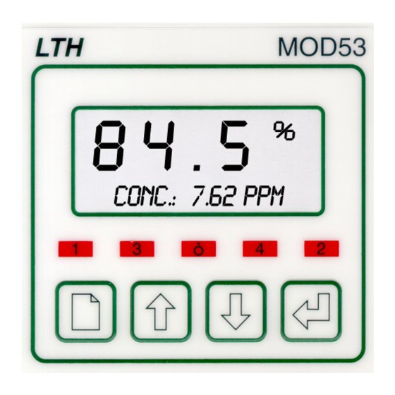
PROGRAMMING BUTTONS THE FRONT PANEL The MOD53 uses a versatile dot matrix character LCD to display all of the settings and readings. The seven segment digits at the top of the display indicate the primary measured value during normal operation. The six character display to the right of these indicates the units of measurement when a value is being displayed. -
Page 31: The Menu System
When the instrument is switched on, it will default to the main display menu. The user interface to the MOD53 is arranged as a menu structure, a summary of which is printed as a fold out sheet at the back of this guide. Movement around this menu structure is achieved using the “PAGE”, “UP”... - Page 32 5 User Interface Enter the access code as follows. { Note : “Outlined” text represents flashing digits/characters on the display }. 0 0 0 0 0 0 0 0 0 0 0 0 0 0 0 0 Access Code ? Press “ENTER”...
- Page 33 5 User Interface 6 3 0 0 0 0 Access Code ? Use the “UP” and “DOWN” keys to change the third digit 6 3 0 0 0 0 Access Code ? Press “ENTER” to select the next digit 6 3 7 6 3 7 6 3 7 6 3 7...
- Page 34 5 User Interface Pressing the “PAGE” key from within a menu will return the unit to the menu’s header, subsequent presses of the “PAGE” key will advance to the next menu. When the last menu is reached the unit will return to the normal display mode. Using the “PAGE”...
-
Page 35: Unit Configuration
5 User Interface UNIT CONFIGURATION Editing of discrete values (such as Set Point Level or Fixed Temperature Input) is performed in the same way as described previously for the access code entry. Changing states (such as Units or Set Point Mode) is achieved in a similar fashion. E.g. - Page 36 5 User Interface For functions such as Calibration and Restoring Setup, press the ”ENTER” key to initiate the function, the system will then ask for confirmation. Press “ENTER” to continue or “UP” or ”DOWN” to cancel the function. e.g. Select the required function and press the “ENTER”...
- Page 37 5 User Interface This page intentionally blank...
-
Page 38: Main Display
6 Main Display 6 Main Display The normal mode of operation is to display the sensor reading on the top row and a secondary reading on the bottom row. Using the “UP” and “DOWN” keys the user can cycle through the secondary parameters (those available depend upon the instrument options and configuration). - Page 39 6 Main Display 6 0 . 0 6 0 . 0 6 0 . 0 6 0 . 0 Sensor + Set Point 1 Low (When SP1 Trigger = Band or Latch) SP1L : 2.00% Set Points 2 & 3 are displayed here in the same format as for Set Point 1 but are excluded here for brevity.
- Page 40 6 Main Display 6 0 . 0 6 0 . 0 6 0 . 0 6 0 . 0 Sensor + Current Output A (if fitted) Output A : 12.76mA 6 0 . 0 6 0 . 0 6 0 . 0 6 0 .
- Page 41 6 Main Display This page intentionally blank...
-
Page 42: Parameters
7 Parameters 7 Parameters The “Parameters” menu contains the basic configurations for the sensor inputs Parameters Menu Header Parameters Units : % Sat Display Units mm Hg Current Sensor Type Probe : Galvanic Polargraphic Temperature Display Units Temp Units : °C °F Continued on next page .. - Page 43 7 Parameters Temperature Compensation Mode. Only present if temperature sensor (T Input) is enabled under “Configuration” menu page. TC Mode : Auto (Otherwise defaults to “Manual”) Manual °C + 2 5 . 0 + 2 5 . 0 + 2 5 . 0 + 2 5 .
-
Page 44: Units
Simulate : 12.00mA UNITS The MOD53 primary display can be setup to display in % (saturation), ppm (concentration), pO2 (partial pressure of Oxygen) or input current. This is achieved by simply setting the appropriate units. The relationship between these three parameters is determined by several factors including temperature, pressure and the salinity of the solution being measured. -
Page 45: Sensor Type
7 Parameters SENSOR TYPE The MOD53 can scale its input readings to operate with either a Galvanic (Mackereth) or Polargraphic (Clark) sensor. This enables the instrument to be used with a variety of different manufacturers’ sensors. Both types of sensor provide a current output, but Polargraphic sensors require a polarising voltage to be applied across the Anode and Cathode. -
Page 46: Pressure Compensation
SIMULATED INPUT The facility exists within the MOD53 to simulate the input sensor levels to test the set point and current output operation. This function allows the user to cycle up and down through the sensor range using the “UP” and “DOWN” keys and display the current output level, with the relays responding accordingly. - Page 47 7 Parameters This page intentionally blank...
-
Page 48: Set Points
8 Set Points 8 Set Points The Set Point configuration is separated into two menus, the first “Set Points 1&2” and the second “Set Points 3&4” (if fitted). The menu structures for Set points 1,2 & 3 are identical, and provide a high level of flexibility in the configuration of the relay outputs. - Page 49 8 Set Points Set Point Mode. This menu will not appear if Trigger is set to “Latch” or SP1 Mode : On/Off “Band”. The mode will default to “On/Off” in this state Set Point 1 Dose Alarm Timer Enable. SP1 Dose Alarm? 0 0 : 3 0 0 0 : 3 0 0 0 : 3 0...
-
Page 50: Set Point Source
SET POINT SOURCE The set point operation on the MOD53 can be configured to operate from one of three sources. The default source is the main sensor input reading, but the set point can also trigger from the temperature input or be used to switch a cleaning device for timed washing of the sensor. -
Page 51: Set Point Mode
Time Proportional Mode The MOD53 provides two forms of pseudo proportional control, which can be used to control the levels to a defined value when used in conjunction with a pump or valve. When the reading deviates from the programmed set point level the relay pulses at a rate proportional to that deviation. -
Page 52: Dose Alarm Timers
8 Set Points The output relay now operates by producing a series of pulses of fixed duration. The pulse rate increases as the measurement moves further from the set point, until it reaches the maximum frequency at the limit of the proportional band. (i.e. 4 ppm in the previous example). -
Page 53: Set Point 4
8 Set Points SET POINT 4 Set Point 4 can be configured as an alarm output triggered by one of a number of events. This can be configured by editing the SP4 trigger, which can be found after the Set Point 3 configuration in the “Set Points 3&4” menu. Set Points 3 &... -
Page 54: Current Output
9 Current Output 9 Current Output The current output menu structure contains all of the necessary setup functions to configure the current output source(s). If one current output is fitted then the menu will be as follows. If two current outputs are fitted they are referred to as A and B respectively. -
Page 55: Input
9 Current Output 2 0 . 0 2 0 . 0 2 0 . 0 2 0 . 0 Span current (20mA) sensor input level Current O/P Span Select state of current output when input source error is detected (i.e. Sensor Input On Error = Fault, Temperature input Over range) 22mA... -
Page 56: Dual Current Outputs
9 Current Output DUAL CURRENT OUTPUTS If the instrument is supplied with two current outputs they are designated A & B respectively. The menu for current output B is identical to A and is displayed after the A menu. PROPORTIONAL CONTROL Many devices such as motor speed controllers, valve actuators, or stroke positioners will accept an analogue 4-20 mA control signal. - Page 57 9 Current Output This page intentionally blank...
-
Page 58: Calibration
10 Calibration 10 Calibration The MOD53 provides the facility within the “Calibration” menu to adjust the sensor inputs and current output levels to tailor the unit to the system in which it is operating. Calibration Menu Header Calibration When “Off-Line” the relays are de- energised and the current outputs held. - Page 59 10 Calibration 2 . 0 0 2 . 0 0 2 . 0 0 2 . 0 0 Enter the sensor pressure at calibration Enter Pressure Sensor Zero (0% Saturation) Calibration. Sensor Zero 1 0 0 . 0 1 0 0 . 0 1 0 0 .
-
Page 60: On-Line/Off-Line Operation
10 Calibration 4-20mA Pressure Input Calibration (Only present if “Pressure Comp.” is set to “Auto” in the Parameters Menu) Pressure Input Current Output Calibration (User adjustment of 0,4 & 20mA output levels) Current Output Reset all of the calibrations to the factory default settings. -
Page 61: Sensor Calibration
10 Calibration SENSOR CALIBRATION Sensor Zero Calibration (Place sensor in 0% saturated solution) Sensor Zero Press to begin calibration The instrument will ask for confirmation Are You Sure? Press to Confirm, any of the other 3 buttons will abandon the sensor calibration. Unit measures input current that equates to the 0% Saturation input level. -
Page 62: Temperature Calibration
10 Calibration TEMPERATURE CALIBRATION To initiate the temperature calibration select the “Temperature“ menu item in the “Calibration” menu and press the “ENTER” key. Temperature offset calibration (Only present if Compensation is Automatic) Temperature The instrument will ask for confirmation Are You Sure? Press to confirm, any of the other 3 buttons abandons the temperature calibration. -
Page 63: Pressure Input Calibration
10 Calibration PRESSURE INPUT CALIBRATION Pressure Input Calibration Pressure Input Press to begin calibration The instrument will ask for confirmation Are You Sure? Press to Confirm, any of the other 3 buttons will abandon the sensor calibration. Set the pressure transmitter output to 4mA. Set Input to 4mA Press “ENTER”... -
Page 64: Current Output Calibration
10 Calibration CURRENT OUTPUT CALIBRATION The user is provided with an opportunity to adjust the current output, to calibrate any equipment that may be being used to monitor the current output signal. To adjust the current output select the “Current Output” menu item in the “Calibration”... -
Page 65: Resetting The User Calibration
10 Calibration RESETTING THE USER CALIBRATION If required the user can reset all of the user calibrations to their default states by selecting the “Reset User Cal.” menu item . Reset all User calibrations to default states Reset User Cal Press “ENTER”... -
Page 66: Save & Restore
11 Save & Restore 11 Save & Restore One of the many new features in the MXD53 series of instruments is the availability to the user of a setup storage and recovery facility. Using these functions the user can save an instrument setup into either of two stores, or restore a previously saved setup from one of the two stores or two default setups. - Page 67 11 Save & Restore Set instrument to default for Galvanic Probe operation. Default Galvanic Set instrument to default for Polargraphic Probe operation. Default Polargraphic To use these functions select the “Save/Restore” menu item and use the ”UP” and “DOWN” keys to select the required function. Pressing the “ENTER”...
-
Page 68: Pressure Input
When the “P Comp” parameter in the “Parameters” menu is set to “Auto” this menu will become available. Pressure menu header Pressure The MOD53 has the ability to support both direct 4-20mA input and 24V loop powered systems by setting this parameter. NB A “User Calibration” is essential in the 24V Input loop mode. - Page 69 Pressure Limit B Input Mode The MOD53 is designed to accept either direct 4-20mA input, or to interface to a 24V loop powered transmitter. Care should be taken when connecting the unit to ensure that the cable resistance is not too great, which will lead to too great a voltage drop over length of the cable.
- Page 70 12 Pressure Input Pressure Damping The facility has been provided to allow the user the dampen the effect of rapid changes in pressure that might lead the unit to activate the set point relays before the sensor has had a chance to react to the change in pressure (which would give a false reading).
- Page 71 12 Pressure Input This page intentionally blank...
-
Page 72: Configuration
The units also includes a configuration menu which sets up some basic operating parameters for the instrument Configuration menu header Configuration The MOD53 has the ability to support multilingual text messaging, this can be selected from this menu. Lan :... - Page 73 13 Configuration 2 5 0 0 2 5 0 0 2 5 0 0 2 5 0 0 The Membrane Correction Factor can be set at this menu parameter. Membrane Correction This function will disable/enable flashing error messages on the main display.
-
Page 74: Sensor Cleaning
14 Sensor Cleaning 14 Sensor Cleaning The set points or current output can be configured to operate a jet spray wash or rotary electrode cleaning system on a timed cycle. Its purpose is to prevent accumulation of particulate matter on the active surfaces of the sensor. cleaning control menus can be accessed form either of the Set Point or Current Output menus, when one or other has been set to cleaning mode. - Page 75 14 Sensor Cleaning When operating in “On-Line” state, “Y” forces the cleaning to wait until all relays are inactive. (Only appears when state = “On-Line”) Cleaning Delay Manually taking the instrument Off-Line will prohibit or terminate a “Clean” cycle. If the instrument is Off-Line when a “Clean”...
-
Page 76: Fault Finding
NOTE : THERE ARE NO USER SERVICEABLE PARTS INSIDE THE UNIT The MOD53 has been designed to include a wide range of self diagnostic test, some of which are performed at switch on, and some on a continuous basis. This guide aims to provide a route to diagnosing and correcting any faults that may occur during normal operation. - Page 77 15 Fault Finding ♦ Where extension cables have been used, try connecting the sensor directly to the instrument. ♦ Check the sensor using a hand held meter. The Sensor Reading Is Incorrect ♦ Check the temperature compensation mode. If the compensation is set to “Manual”...
- Page 78 Due to the Galvanic action of the sensor, the cartridge has a finite life. It will provide at least 12 months of continuous use before replacement becomes necessary. LTH Electronics operates an exchange service for electrodes, but we recommend the purchase of a spare cartridge if the process being monitored is continuous.
- Page 79 15 Fault Finding This page intentionally blank...
-
Page 80: Oe15 Membrane Replacement
16 OE15 Membrane Replacement 16 OE15 Membrane Replacement The electrode membrane is very delicate and may be damaged by careless use. Inspect the electrode periodically for signs of membrane damage and replace it if necessary. Remove the damaged membrane and the two ’O’... - Page 81 16 OE15 Membrane Replacement Place the two ‘O’ rings on the applicator and slide this over the electrode taking care not to touch the membrane covering the silver cathode. Push off the first ‘O’ ring to locate in the top groove without stressing the membrane. Fit the second ‘O’ ring in a similar fashion and trim off the excess membrane not enclosed within the ‘O’...
-
Page 82: Guarantee And Service
Products manufactured by LTH Electronics Ltd are guaranteed against faulty workmanship and materials for a period of three years from the date of despatch, except for finished goods not of LTH manufacture, which are subject to a separate agreement. All sensors made by LTH Electronics Ltd are thoroughly tested to their published specification before despatch. - Page 83 17 Guarantee and Service This page intentionally blank...
-
Page 84: Appendix A - Do Measurement
Appendix A – DO Measurement Appendix A – DO Measurement Sensor Interface The output signal from a Dissolved Oxygen probe is in the form of a constant DC current which is proportional to the partial pressure of the liquid being measured. In a 100% saturated solution at room temperature and pressure, the output from a Galvanic probe will be of the order of hundreds of micro-amps (10 Amps),... - Page 85 Appendix A – DO Measurement Membrane Correction The membrane correction term is defined as follows : A([1/T]-[1/To]) M = e Where : A = Membrane Correction Factor T = Temperature (in °K) To = Temperature at calibration (in °K) The membrane correction factor is specific to each make of probe and characterises the type and thickness of the membrane material in terms of how its permeability to Oxygen varies with temperature.
-
Page 86: Appendix B - Probe Parameters
The following table gives the necessary configuration data for a number of DO probes : Membrane Temperature Bias Probe Type Correction Voltage Sensor Type Factor LTH OE15 1K Thermistor 3965 BJ ProcessProbe 22K Thermistor 2220 +0.675V Hamilton Oxysens 22K Thermistor 2700... - Page 87 Appendix B – Probe Parameters This page intentionally blank...
-
Page 88: Appendix C - Factory Default Setups
Appendix C – Factory Default Setups Appendix C – Factory Default Setups Parameters Galvanic Polargraphic Units % Saturation % Saturation Probe Type Galvanic Polargraphic °C °C Temperature Units Temperature Compensation Automatic Automatic Fixed Temperature Input +25.0°C +25.0°C Fixed Salinity Input 0.00 ppt 0.00 ppt Pressure Compensation... - Page 89 Appendix C – Factory Default Setups Parameters Galvanic Polargraphic SP2 Source Sensor Sensor SP2 Trigger High High SP2 Level (Latch High) 50.0% 50.0% SP2 Latch Low 20.0% 20.0% SP2 Mode On/Off On/Off SP2 Dose Alarm SP2 Alarm Time (mm:ss) 05:00 05:00 SP2 Delay (mm:ss) 00:00...
- Page 90 0.00 Atm 0.00 Atm Calibration Mode On-Line On-Line Calibration Access Configuration Language English English T Input LTH 1K* BJ 22K** Bias Voltage 0.000V +0.675V** Membrane Correction Factor 3965* 2220** Errors Enabled Enabled Input Filter Default for use with the OE15 Probe...
- Page 91 Appendix C – Factory Default Setups This page intentionally blank...
-
Page 92: Appendix D - Customer Setup
Appendix D – Customer Setup Appendix D – Customer Setup Instrument Serial No. _____________________ Sensor Serial/Type No. : _____________________ Parameters Units Probe Type Temperature Units Temperature Compensation Fixed Temperature Input Fixed Salinity Input Pressure Compensation Pressure Units Fixed Pressure Input Set Point 1 SP1 Source SP1 Trigger... - Page 93 Appendix D – Customer Setup Set Points 2 - 4 SP2 Source SP2 Trigger SP2 Level (Latch High) SP2 Latch Low SP2 Mode SP2 Dose Alarm SP2 Alarm Time (mm:ss) SP2 Delay (mm:ss) SP2 Hysteresis (% of SP Level) SP2 Cycle Time (mm:ss) SP2 Proportional Band (% of range) SP3 Source...
- Page 94 Appendix D – Customer Setup Current Output Input A Output A Output A Zero Output A Span Input B Output B Output B Zero Output B Span Pressure Input Mode Units 4mA level 20mA Level Damping Limit A (“From”) Limit B (“To”) Calibration Mode Calibration Access...
- Page 95 Appendix D – Customer Setup This page intentionally blank...
-
Page 96: Appendix E - Calibration
Appendix E – Calibration Appendix E – Calibration Calibration Procedures Normal good practices should be observed when calibrating DO systems. When the instrument is first connected to the oxygen sensor, i.e. when the unit is first installed, or whenever the oxygen sensor is changed or the membrane replaced, the user should perform a zero check and span calibration of the system using the following procedure. - Page 97 Appendix E – Calibration • If the sensor responds quickly enough, check that within another 3 minutes the current reading has fallen to virtually zero (less than 5µA). • If the current reading is greater than 5µA, select the “Zero Cal” function form the main menu, or from the calibration menu.
-
Page 98: Appendix F - Temperature Sensor Data
Appendix F – Temperature Sensor Data The table below lists approximate resistance values of temperature sensors that may be used with the MXD53 series. Not all options are available on all models. Temperature PT1000 LTH 1K BJ 22K (° ° ° ° C) RTD** Thermistor Thermistor 1000.0Ω... - Page 99 Appendix F – Temperature Sensor Data This page intentionally blank...
-
Page 100: Appendix G - Pressure Conversions
Appendix G – Pressure Conversions Appendix G – Pressure Conversions The following table provides conversions between all the common pressure units... - Page 101 Appendix G – Pressure Conversions This page intentionally blank...
-
Page 102: Appendix H - Oxygen Solubility
Appendix H – Oxygen Solubility Appendix H – Oxygen Solubility Solubility of Oxygen in Pure water Temp ppm O Temp ppm O 14.59 8.90 14.19 8.73 13.81 8.55 13.44 8.40 13.08 8.24 12.75 8.08 12.42 7.94 12.12 7.80 11.82 7.66 11.54 7.54 11.27... - Page 103 Appendix H – Oxygen Solubility The solubility of oxygen in pure water varies considerably with temperature. The table on the previous page gives the variation of oxygen concentration in ppm (=mg/litre) across a temperature range of 0 – 40 C in pure water at equilibrium with water vapour saturated air at 1 Atmosphere standard pressure (= 760 mm Mercury).
-
Page 104: Appendix I - Error Messages
The software runs a checksum test on the program memory store at power on, to ensure that the integrity of the software has not been compromised. Switch the unit off then on again. If the error message persists call LTH Electronics or authorised local distributor. E03 : External RAM Read/Write Error Try switching the unit off then on again. - Page 105 Appendix I – Error Messages Sensor Input Errors E31 : Sensor Input Limit (+ve) The ADC input is greater than the maximum measurable input level. (+2.5V) E32 : Sensor Input Limit (-ve) The ADC input is lower than the minimum measurable input level (-2.5V) E33 : Sensor Input Over-range...
- Page 106 Appendix I – Error Messages Current Output Errors E41 : Current Output Hardware Fault The current output circuit has detected an error in the output, this is most commonly due to either a broken loop or too large a load resistor.
- Page 107 Appendix I – Error Messages This page intentionally blank...
-
Page 108: Index
Index Index Dimensions Panel Mount Unit....9 Access Entry....30 Surface Mount Unit ..19 Active pressure comp.17, 27 Display......29 Dose Alarm......48 Bell Symbol..... 30 EMC ........2 EMI ........8 Calibration....... 57 0% Saturation....60 Errors 100% Saturation..58, 60 Disabling ......72 Access to..... 59 Messages.....30 Current Output.. - Page 109 Index Polargraphic....44 Hysteresis ....48, 50 Level ......47 ppm concentration ..43 Mode ......48, 52 Pressure ......43 On/Off Mode....50 Compensation . 17, 27, 44 PP Mode ......50 Compensation Mode ... 42 Proportional Band ..49, 52 Damping ...... 69 Source......49 Input Calibration ..
- Page 110 LTH Electronics Ltd Chaul End Lane Luton Bedfordshire LU4 8EZ United Kingdom Telephone : +44 (0) 1582 593693 Fax : +44 (0) 1582 598036 e-mail : sales@lth.co.uk web : www.lth.co.uk...
Need help?
Do you have a question about the MOD53 and is the answer not in the manual?
Questions and answers