
Related Manuals for EMX WEL-200


Summary of Contents for EMX WEL-200
- Page 1 WEL-200 W I R E L E S S E D G E L I N K 4564 Johnston Parkway, Cleveland, Ohio 44128 P. 800 426 9912 F. 216 518 9884 Sales Inquiries: salessupport@emxinc.com Technical Support: technical@emxinc.com www.emxinc.com...
-
Page 2: Table Of Contents
Cautions and Warnings Contents Specifications Product Overview Controls and Indicators Connections Installation and Operation Troubleshooting Ordering Information WEL-200™ Operating Instructions Document no. 10320104 Revision 2.0 3-1-18... -
Page 3: Cautions And Warnings
Copyright Notice All rights reserved. Unless otherwise stated, the material within this document is copyright of EMX Industries Inc. No part may be reproduced, in whole or in part, without the specific written permission of EMX Industries Inc. Cautions and Warnings 1. -
Page 4: Specifications
140mm (5.5”) x 34mm (1.3”) x 180mm (7.0”) x 32mm (1.3”) x Dimensions (L x W x H) 90mm (3.5”) 67mm (2.6”) Weight 200g (7 oz.) 170g (6 oz.) Connections 12 terminals (18-26AWG) 2 terminals (18-26AWG) WEL-200™ Operating Instructions Document no. 10320104 Revision 2.0 3-1-18... -
Page 5: Product Overview
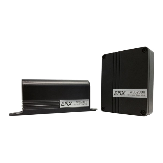
Figure 1 - WEL-200T (transmitter) Figure 2 - WEL-200R (receiver) The EMX WEL-200 system provides a complete wireless solution for interfacing sensing edges with gate and door operators, while ensuring compliance with 2018 UL325 monitoring standards. Each transmitter can run for up to two years on two AA lithium batteries. -
Page 6: Controls And Indicators
- Terminates the COM/NO terminals with a 10k resistor when jumper is placed in the lower position 10. Earth ground - Connection point for earth ground 11. Terminal block Receiver I/O (see Table 1 in Connections) WEL-200™ Operating Instructions Document no. 10320104 Revision 2.0 3-1-18... - Page 7 - Blinks twice every two seconds if not connected, once if connected - Blinks once every second when edge is activated 3. Terminal block - Interface for safety edge 4. Connection switch - Connects/disconnects transmitter from receiver WEL-200™ Operating Instructions Document no. 10320104 Revision 2.0 3-1-18...
-
Page 8: Connections
RELAY CLOSE COM Common connection for CLOSE direction Normally open connection for CLOSE RELAY CLOSE NO direction 12-24 VDC/VAC power input (non- 11/12 POWER polarized) EARTH EARTH Earth ground connection WEL-200™ Operating Instructions Document no. 10320104 Revision 2.0 3-1-18... -
Page 9: Installation And Operation
TXs. This can be accomplished by extending the top of the RX approximately 1” above the top edge of the operator, mounting on top of the operator, or on a side that is in line of site with both edge transmitters. WEL-200™ Operating Instructions Document no. 10320104 Revision 2.0... - Page 10 Using a second wrench, tighten the sealing nut to 40 in. lbs. until the cable is securely held in place. b. If the cable has different diameter point the cable ingress down to prevent water penetration. WEL-200™ Operating Instructions Document no. 10320104 Revision 2.0 3-1-18...
- Page 11 2.6.3. If the transmitter fails to connect, it will return to its initial state, with the LED flashing twice every two seconds. If this occurs, repeat step 2.6. If the transmitter will not connect, proceed to the troubleshooting section. WEL-200™ Operating Instructions Document no. 10320104 Revision 2.0...
- Page 12 3. To remove a connection from the transmitter, hold down the connection button. The LED will turn on solid for several seconds, and then blink twice every 2 seconds when disconnected. WEL-200™ Operating Instructions Document no. 10320104 Revision 2.0 3-1-18...
-
Page 13: Troubleshooting
The system status LED (next to the power LED) can be used to compare the flashes. The LED for an unassigned channel will flash at the same rate as the status LED. System status/unassigned channel indicator 0.25s 0.5s 0.75s 1.25s 1.5s 1.75s WEL-200™ Operating Instructions Document no. 10320104 Revision 2.0 3-1-18... - Page 14 If the transmitter batteries fall below their ideal operating voltage , the LED for its assigned channel will turn on for 0.25 seconds, 3x per cycle. Transmitter battery low 0.25s 0.5s 0.75s 1.25s 1.5s 1.75s WEL-200™ Operating Instructions Document no. 10320104 Revision 2.0 3-1-18...
- Page 15 Transmitter is inactive 0.25s 0.5s 0.75s 1.25s 1.5s 1.75s Dimensional Outline: Receiver WEL-200™ Operating Instructions Document no. 10320104 Revision 2.0 3-1-18...
- Page 16 Dimensional Outline: Transmitter WEL-200™ Operating Instructions Document no. 10320104 Revision 2.0 3-1-18...
-
Page 17: Ordering Information
EMX Industries option of a part or parts found not conforming to the warranty. In no event shall EMX Industries Inc. be liable for damages, including but not limited to damages resulting from non-conformity, defect in material or workmanship. - Page 18 4564 Johnston Parkway Cleveland, Ohio 44128 United States of America www.emxinc.com Technical Support: (216) 834-0761 technical@emxinc.com Sales: (216) 518-9888 Fax: (216) 518-9884 salessupport@emxinc.com WEL-200™ Operating Instructions Document no. 10320104 Revision 2.0 3-1-18...
Need help?
Do you have a question about the WEL-200 and is the answer not in the manual?
Questions and answers