
Related Manuals for Leica Geosystems iCONgrade iCP32
Summary of Contents for Leica Geosystems iCONgrade iCP32
- Page 1 Leica iCONgrade iCP32 User Manual Version 1.0 English HITCHDOC HE1596_R0; OWNERS MANUAL, LEICA iCP32...
- Page 2 The type and serial number of your products are indicated on the label on the base of the unit. Enter the model and serial number in your manual and always refer to this information when you need to contact your agency or Leica Geosystems authorised service workshop. Type: iCP32 Control Box Serial No.:...
- Page 3 Symbols The symbols used in this manual have the following meanings: Type Description Danger Indicates an imminently hazardous situation which, if not avoided, will result in death or serious injury. Warning Indicates a potentially hazardous situation or an unintended use which, if not avoided, could result in death or serious injury.
-
Page 4: Table Of Contents
iCONgrade, Table of Contents Table of Contents In this manual Topic Page Product Overview Product Description and Features Getting Started Sensor Setup Keys Operation Pre-power up checks 2.1.1 Best operation practice for Grader Systems 2.1.2 Mast orientation 2.1.3 No Articulation, circle center shift, or wheel lean on Grader 2.1.4 Grader blade cushioning off 2.1.5... - Page 5 Care and Transport General Notices Transport Storage Cleaning and Drying Safety Directions General Intended Use Limits of Use Responsibilities Hazards of Use Electromagnetic Compatibility EMC Labelling Technical Data iCP32 Technical Data Conformity to National Regulations International Limited Warranty, Software License Agreement iCONgrade, Table of Contents...
-
Page 6: Product Overview
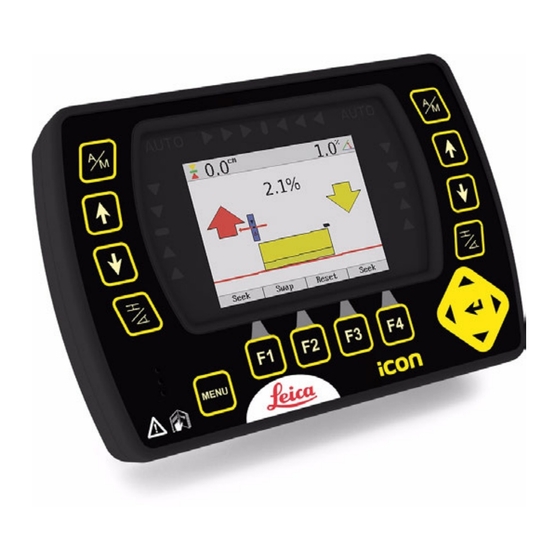
iCONgrade, Product Overview Product Overview Product Description and Features General The control panel has keys surrounding the screen for user input. The 3.5" colour display, incorporates a state of the art LCD colour screen, making it easy to use, even in bright, sunny conditions. - Page 7 iCP32 control panel iCP32_001 a) Graphical display e) Menu key b) Grade indication LEDs f) Function keys c) Left/Right side sensor setup g) Enter key d) Speaker Warning This product may be installed on building machinery only by an appropriately trained and qualified specialist.
- Page 8 iCONgrade, Product Overview Warning Unauthorized modification of machines by mounting the product may alter the function and safety of the machine. Precautions: Follow the instructions of the machine manufacturer. If no appropriate instruction is avail- able, ask the machine manufacturer for instructions before mounting the product. Keys Up key Down key...
- Page 9 Display iCP32_002 a) Side shift alignment indication b) Above grade c) Left/Right on-grade indication d) Below grade iCONgrade, Product Overview...
- Page 10 iCONgrade, Product Overview MMB1300 Cradle a) Power and data transfer LED indicators b) Holding magnets c) On/off switch d) Release key for control panel iCP32_003...
-
Page 11: Getting Started
Getting Started System start To get the system started complete the following steps: 1. Snap control panel onto cradle. To connect the control panel to the cradle: 1. Put the control panel on the holding hooks in the bottom of the cradle. 2. - Page 12 iCONgrade, Product Overview 2. Turn on the control panel. To turn the system on and off, use the power switch on the right side of the cradle. This is the master switch for the entire system. Removing the panel will also turn off the power.
-
Page 13: Sensor Setup Keys
Sensor Setup Keys Sensor setup keys The sensor setup keys are used to choose the type of sensor that the system should run with, and to find and set the reference point for that sensor. The left and right hydraulic channel has four sensor setup keys each: •... - Page 14 iCONgrade, Product Overview External switch for Toggle the master switch to AUTO to enable automatic control on all chan- Dozer nels selected on the control panel. Toggling the master switch to MAN places all channels in manual control regardless of selection on the control panel.
- Page 15 iCONgrade, Product Overview...
-
Page 16: Operation
iCONgrade, Operation Operation Pre-power up checks State of the machine Before the system is powered up, please check the state of the machine to make sure that it is configured to function correctly. Check and set When? To learn how, see … Mast perpendicular to wheelbase. -
Page 17: Best Operation Practice For Grader Systems
2.1.1 Best operation practice for Grader Systems Hint for best Below you will find a list of things that will help achieve the best results when operating a performance Grader system. • Ensure that mast is perpendicular to the wheelbase, or use a mast slope sensor. •... -
Page 18: Mast Orientation
iCONgrade, Operation 2.1.2 Mast orientation Mast orientation For Dozers and Graders without mast slope sensor, you must make sure that the mast is at the “as measured” position (that is, the position the mast or masts were in during the mast measure up). -
Page 19: No Articulation, Circle Center Shift, Or Wheel Lean On Grader
2.1.3 No Articulation, circle center shift, or wheel lean on Grader Articulation, circle For Grader systems that rely on the cross slope sensor, and a single elevation sensor, you Centershift, and wheel must make sure that the machine is not articulated and that there is no side shift applied lean to the circle. - Page 20 iCONgrade, Operation Circle center shifted Wheel leaned Wheel lean introduces an error in the reading from the mainfall sensor. Articulation and circle Centershift introduce unmeasured blade rotation. Operating with wheel lean, circle centershift or articulation can cause inaccuracy in the cross slope being cut.
-
Page 21: Grader Blade Cushioning Off
2.1.4 Grader blade cushioning off Blade cushioning off Using a Grader’s blade cushioning device at the same time as the blade is being automatically controlled by the system results in poor automatic control performance. Make sure that blade cushioning, if installed, is turned off before working with automatic controls. -
Page 22: No Blade Rotation On Dozer
iCONgrade, Operation 2.1.5 No blade rotation on Dozer Dozer blade rotation For Dozer systems that use a cross slope sensor you must make sure that the blade is square to the machine (not rotated). Dozer blade square Dozer blade rotated Operating with a rotated blade can cause inaccuracy in the cross slope being cut. -
Page 23: Select The Input Source
Select the Input Source Sensor selection 1. Push the left or right key to open the sensor selection menu. Following screen appears: iCONgrade, Operation... - Page 24 iCONgrade, Operation 2. Use the keys to scroll through the available sensors. a) If the sensor is connected and active it will show up in black. b) If it’s not connected or inactive it will show in red. 3. Highlight the sensor that is going to be used and exit the sensor selection menu by pressing...
- Page 25 4. The chosen sensor is indicated by a small icon in the upper corner of the display, and by an icon shown on the blade in relation to the actual placement of the sensor. Example: a) Laser indication b) Cross Slope A cross slope is selected in the right side and in the left side a Laser Sensor is selected.
-
Page 26: Setting A Reference Height
iCONgrade, Operation Setting a Reference Height Inspection When a sensor is selected the control panel automatically uses the last set reference height for that sensor. There are two ways to change the reference: • Manual mode • Seek mode Manual mode Use the keys to change the reference height up or down. - Page 27 Automatic detection of For systems with a MPM700 Electric Mast, entering seek mode will start an automatic search the laser beam for the laser beam. If the laser sensor is out of beam the operator can select in which direction the mast should start moving to look for the laser beam using the keys.
-
Page 28: Using The Mus1300 Tri-Sonic Sensor
iCONgrade, Operation Using the MUS1300 Tri-Sonic Sensor Using Tri-Sonics The Tri-Sonic can also measure the horizontal distance to a stringline and therefore it can be used to control the sideshift on a grader. To do that, complete the following steps: 1. - Page 29 Select between the different modes: • Ground Mode • Edge Mode • Stringline Press the key to toggle between the modes. Once selected press the key. Following screens will appear by pressing the up ( ) or down ( ) Enter key to toggle between the screens.
- Page 30 iCONgrade, Operation Stringline describes the window where the Tri-Sonic will work within certain range. All readings outside of this range will be ignored. Sideshift works only with the Edge and Stringline modes. 6. Go to the Sideshift menu option and set it to Yes. 7.
- Page 31 11. Press the Side A/M function key to enable the automatic sideshift control. iCONgrade, Operation...
-
Page 32: Installation And Set Up Tri-Sonic Sensor
iCONgrade, Operation 2.4.1 Installation and Set Up Tri-Sonic Sensor Mounting the Tri-Sonic The Tri-Sonic can be installed quickly and easily with the simplest of tools. Sensor Mount a support in a suitable location that is adjustable for height and lateral motion. This will enable setting up of the Tri-Sonic over any reference. - Page 33 Stringline and Edge For stringline sensing, the Tri-Sonic must be positioned across the reference wire. The Auto- sensing matic Side Shift control of the Tri-Sonic will keep the sensor always over the reference using the hydraulics of the third valve section to regulate the Blade in and out. Mounting the Tri-Sonic Normal operation on the support...
-
Page 34: Operation With The Tri-Sonic Sensor
iCONgrade, Operation Caution System Components can protrude from the machine, which could lead to bodily injury and/or product damage. Precautions: Exercise caution in operation to avoid striking any objects or persons near the working area. 2.4.2 Operation with the Tri-Sonic Sensor iCP32 system flexibility Multifunctional and multitask - iCP32 system can be operated in various combinations for the most demanding job requirements. - Page 35 Reference ground 90° a) Side View b) Ground Reference stringline 90° a) Side View b) String iCONgrade, Operation...
- Page 36 iCONgrade, Operation Reference edge 90° a) Side View b) Edge Setting up the Tri-Sonic When setting the Tri-Sonic sensor over a reference (string, curb, or previous pass), the best performance will be achieved when the sensor is positioned square to the reference (not turned or leaning).
-
Page 37: Swap Function
2.4.3 Swap Function Set up and operation The swap function allows the operator to quickly and easily swap sensors, turn the machine around, and grade in the opposite direction by following the previously pass. There are two levels to the swap function available: •... - Page 38 iCONgrade, Operation It is possible to have different heights and mode settings for the two Tri-Sonic sensors.
-
Page 39: Using The Laser Sensor
Using the Laser Sensor Laser Sensor The Laser Sensor is used to measure the elevation of the blade. This is done by measuring the distance from where the laser beam is hitting MLS700 the laser and the centerline on the Laser Sensor. When the Laser Sensor detects a laser beam this is indicated on the display by a red line through the laser icon. - Page 40 iCONgrade, Operation Laser Sensor and To use the Laser Sensor with a power mast for controlling the elevation of the blade MPM700 Electric Mast complete the following steps: 1. Select the Laser Sensor in one of the sides. 2. Place the cutting edge of the blade at the wanted height. 3.
-
Page 41: Sp14 Sensor
SP14 Sensor Introduction The SP sensor is a new technology in machine automation. It improves smoothness obtained with GPS, PowerTracker and laser reference sensors. In addition, the dozer can be operated with increased speed compared to a system without SP technology. ... - Page 42 iCONgrade, Operation Benefits from using the For a system with GPS, SP technology results in greater smoothness, increased operation SP14 Sensor speed and a system that is more robust against poor GPS coverage. For a system with PowerTracker, SP technology results in greater smoothness, increased operation speed and a system that is more robust against losing the prism in case of the beam being interrupted.
-
Page 43: Sensors
3D Sensors How to set 3D sensor Select 3D Height (press the left or right (sensor) key once), and then press the Adjust type function key to enter the adjust menu. Note that it's only the current selected sensor in either left or right side that is adjusted. - Page 44 iCONgrade, Operation To select 3D Slope, Press the left or right (sensor) key once, and then press the Adjust function key to enter the adjust menu. Note that it's only the current selected sensor in either left or right side that is adjusted.
-
Page 45: Setting The Value For Gain And Deadband
Setting the Value for Gain and Deadband Adjust the gain and To adjust the gain and deadband of each of the sensors complete the following steps: deadband 1. Press the left or right key once, and then press the Adjust function key to enter the adjust menu. - Page 46 iCONgrade, Operation Gain This is the scaling of hydraulic speeds for each of the sensors. To enter Gains select the Lower Left or Lower Right buttons to open up the available sensors. Select appropriate sensor and then the key (depending on left or right side) to enter the Adjust Menu.
- Page 47 2D and 3D cross slope sensor: This should be measured 1,5 meters from the centre of the blade. Press the Test button to adjust the value so that it corresponds to the below distances. For example, during 2 seconds of movement, the blade should move 8 cm for 3D cross-slope on Dozer. Sensor Dozer Grader...
-
Page 48: Sensor Calibration Wizard
iCONgrade, Operation Sensor Calibration Wizard Enter the Sensor In order to maintain the correct calibration of the sensors, the Sensor Calibration Wizard Calibration Wizard should be run periodically due to blade wear. This should also be done when changing the blade wear edges or changing tires on a grader, as this will change the mainfall slope. This is done by entering the calibration wizard: Menu ->... - Page 49 Warning Screen If any sensors are not installed or not connected a warning screen will appear. Sensor Calibration Park the machine on a flat, hard and level surface, preferably a paved road or similar. 2. step This will facilitate turning the machine around and proper machine alignment. If the machine is already aligned properly and is ready for calibration, skip ahead by pressing “Skip”...
- Page 50 iCONgrade, Operation Sensor Calibration Straighten the machine’s front wheels and articulation. This ensures correct values for 3. step calibrating the mainfall sensor. Select“Next” when complete. Sensor Calibration Centre the machine link bar. It must then be set in its centred position for proper Cross 4.
- Page 51 Sensor Calibration Centre the Blade Sideshift, ensuring the distance from the machine base to the blade tip 5. step is the same on both sides. This is important for the measurements in the next step. Select “Next” when complete. Sensor Calibration Rotate the blade so that the distance from the swivel to each blade tip is the same.
- Page 52 iCONgrade, Operation Sensor Calibration Mark the positions of the wheels on the ground and place the blade gently on solid blocks 7. step or other solid reference, ensure the blade has not rotated or sideshift has been altered. Select “Next” when complete. Sensor Calibration The rotation sensor will automatically calibrate, while at the same time collecting Mainfall 8.
- Page 53 Sensor Calibration Turn the machine around and place the blade gently on the same blocks or reference as 9. step before, ensuring that the blade is not rotated or sideshift has altered. Align the wheels using the markings from the previous step. This is important for the correct measure- ment of the Mainfall and Cross Slope values.
- Page 54 iCONgrade, Operation Sensor Calibration The calibration routine is complete. 11. step Save the calibrated values and exit the wizard by pressing “Save”. To exiting the wizard without saving, press “Exit”.
-
Page 55: Machine Setups
2.10 Machine Setups Grader Setup MLS700 MLS700 a) iCP32 Control panel b) MMB1300 Cradle c) External Multi Switch d) Cross slope sensor e) Rotation sensor f) Laser receiver g) MPM700 Electric Mast/manual mast h) Sonic Tracker i) MJB1301 Junction box Grader j) Hydraulic valve k) Machine battery... - Page 56 iCONgrade, Operation Dozer Setup MLS700 MLS700 a) iCP32 Control panel b) MMB1300 Cradle c) External Switch for Dozer d) Laser receiver e) MPM700 Electric Mast/manual mast f) MJB1300 Junction box Dozer g) Machine battery h) Hydraulic valve i) Cross slope sensor or SP14 Sensor j) Remote junction box k) Remote display...
- Page 57 iCONgrade, Operation...
-
Page 58: Care And Transport
iCONgrade, Care and Transport Care and Transport General Notices General information Servicing the system only requires a minimum of time. All electronic components are enclosed in robust housings to safeguard them against mechanical damage. Periodic checks If any iCP32 components are subjected to severe impact, be sure to check for proper oper- ation prior to performing any work with the system. -
Page 59: Cleaning And Drying
Cleaning and Drying Product • Blow off dust. • Use a clean, soft, lint-free cloth for cleaning. If necessary, moisten the cloth with water or pure alcohol. Do not use other liquids; these may attack the polymer components. Cables and Plugs Keep plugs clean and dry. -
Page 60: Safety Directions
• Modification or conversion of the product. • Use after misappropriation. • Use of products with obviously recognizable damages or defects. • Use with accessories from other manufacturers without the prior explicit approval of Leica Geosystems. -
Page 61: Limits Of Use
Responsibilities Manufacturer of the Leica Geosystems AG, hereinafter referred to as Leica Geosystems, is responsible for product supplying the product, including the user manual and original accessories, in a completely safe condition. -
Page 62: Hazards Of Use
Safety Directions Manufacturers of non The manufacturers of non Leica Geosystems accessories for the product are responsible for Leica Geosystems developing, implementing and communicating safety concepts for their products, and are accessories also responsible for the effectiveness of those safety concepts in combination with the Leica Geosystems product. - Page 63 Caution Installing near mechanically moving machine components may damage the product. Precautions: Deflect the mechanically moving machine components as far as possible and define a safe installation zone. Warning Beware of inadequate steering if machine is defective like after a crash or other damaging events or alterations to the machine.
- Page 64 iCONgrade, Safety Directions Caution Watch out for erroneous measurement results if the product has been dropped or has been misused, modified, stored for long periods or transported. Precautions: Periodically carry out test measurements and perform the field adjustments indicated in the user manual, particularly after the product has been subjected to abnormal use and before and after important operations.
- Page 65 Always prevent access to the product by unauthorised personnel. Product specific treatment and waste management information can be received from your Leica Geosystems dealer. iCONgrade, Safety Directions...
-
Page 66: Electromagnetic Compatibility Emc
Warning Electromagnetic radiation can cause disturbances in other equipment. Although the product meets the strict regulations and standards which are in force in this respect, Leica Geosystems cannot completely exclude the possibility that other equipment may be disturbed. Caution There is a risk that disturbances may be caused in other equipment if the product is used in conjunction with accessories from other manufacturers, for example field computers, personal computers, two-way radios, non-standard cables or external batteries. - Page 67 Disturbances caused by electromagnetic radiation can result in erroneous measurements. Although the product meets the strict regulations and standards which are in force in this respect, Leica Geosystems cannot completely exclude the possibility that the product may be disturbed by very intense electromagnetic radiation, for example, near radio transmitters, two-way radios or diesel generators.
-
Page 68: Labelling
Safety Directions Labelling Labelling iCP32 Control Panel iCP32 Grading 2D Panel P/N: 798669 Leica Geosystems AG 797050 CH - 9435 Heerbrugg Made in Denmark 20XX S/N: xxxxxxxx xxxxxxxx Power 12 - 24 V DC, 6A max. iCP32_007 Labelling MMB1300... - Page 69 Labelling MJB1300 TYPE: MJB1300 Junction Box P/N: 764838 Leica Geosystems AG 764838 CH - 9435 Heerbrugg Made in Denmark 20XX S/N: XXXXXXXX 131441XX Power 12 - 24 V DC, 6A max. iCP32_008 Labelling MJB1301 TYPE: MJB1301 Junction Box P/N: 764839...
- Page 70 Safety Directions Labelling MLS700 Laser Receiver TYPE: MLS700 P/N: 760862 Leica Geosystems AG 760862 CH - 9435 Heerbrugg Made in Denmark 20XX S/N: XXXXXXXX 131441XX Power 12 - 24 V DC, 6A max. iCP32_010...
- Page 71 Labelling MPM700 Power Mast TYPE: MPM700 P/N: 760863 Leica Geosystems AG 760863 CH - 9435 Heerbrugg Made in Denmark 20XX S/N: XXXXXXXX 131441XX Power 12 - 24 V DC, 6A max. iCP32_011 iCONgrade, Safety Directions...
- Page 72 Art.No. Type: MUS1300 Tri-Sonic 764031 Power: 11-30V , 0.5A max S.No. Leica Geosystems AG ..CH-9435 Heerbrugg Manufactured: 2010 Made in Switzerland Patents: U.S. 5.327.345 4.733.355 This device complies with part 15 of the FCC Rules.
- Page 73 Labelling MSS1300 TYPE: MSS1300 Cross Slope Sensor P/N: 764842 Leica Geosystems AG 764842 CH - 9435 Heerbrugg Made in Denmark 20XX S/N: XXXXXXXX 131441XX Power 12 - 24 V DC, 6A max. iCP32_014 Labelling SP14 SP TYPE: SP 14 Sensor...
-
Page 74: Technical Data
iCONgrade, Technical Data Technical Data iCP32 Technical Data The iCP32 system is designed to operate from standard vehicle power systems at 24V DC - check to ensure proper connection and polarity. iCP32 Control Panel Parameter Specification Power Supply The iCP32 is supplied from the cradle MMB1300 Power consumption <... - Page 75 MJB1300 and MJB1301 Parameter Specification Junction Box Voltage range 24 V DC (nom.) Nominal voltage 24 V DC, Range 10 V-30 V Power consumption < 0.5 A with no sensors and valve connected Dimensions MJB1300: 13.8 x 18.3 x 6.4cm MJB1301: 14.5 x 18.3 x 6.4cm Weight 2 kg...
- Page 76 iCONgrade, Technical Data MUS1300 Tri-Sonic Parameter Specification Dimensions 17.2 x 18.3 x 14 cm Weight 2.5 kg Accuracy within ±0.125 cm @ 30.5 cm Input voltage 11 to 30 V DC Power Consumption 0.5 A max. MPM700 Electric Mast Parameter Specification Voltage range 24 V DC (nom.)
- Page 77 Parameter Specification Travel 1.4 m Scale Metric/Inch Weight 14 kg MLS700 Laser Receiver Parameter Specification Voltage range 24 V DC (nom.) Nominal voltage 24 V DC, Range 11 V-30 V Power consumption < 500 mA Dimensions 28 x 12 x 7.2 cm (without mounting bracket) Weight 2.5 kg (incl.
- Page 78 iCONgrade, Technical Data MSS1300 Cross Slope Parameter Specification Sensor Voltage range 24 V DC (nom.) Nominal voltage 24 V DC, Range 10 V-30 V Power consumption < 0.25 A Dimensions 15.3 x 8.7 x 3.9 cm Weight 0.855 kg Accuracy cross slope ±0.1 % slope at ±25°...
- Page 79 MRS1300 Rotation Parameter Specification Sensor Voltage range 24 V DC (nom.) Nominal voltage 24 V DC, Range 10 V-30 V Power consumption < 0.25 A Dimensions Ø16.0 x 22.6 x 5.9 cm Weight 1.56 kg Working range 0-360° Environmental Temperature specifications Type Operating temperature [°C] Storage temperature [°C]...
- Page 80 iCONgrade, Technical Data Protection against water, dust and sand Type Protection iCP32 Control Panel IP67 MMB1300 Cradle IP54 MJB1301 Junction Box IP67 MJB1300 Junction Box IP67 MPM700 Electric Mast IP45 MLS700 Laser Receiver IP68 MUS1300 Tri-Sonic IP54 SP14 SP Sensor IP68 MSS1300 Cross Slope Sensor IP68 MRS1300 Rotation Sensor...
-
Page 81: Conformity To National Regulations
Conformity to National Regulations Conformity to national Hereby, Leica Geosystems AG, declares that the iCP32 control panel is in regulations compliance with the essential requirements and other relevant provisions of the applicable European Directives. For the declaration of conformity please contact your Leica Geosystems distributor. -
Page 82: International Limited Warranty, Software License Agreement
Leica Geosystems. Such software is protected by copyright and other laws and its use is defined and regulated by the Leica Geosystems Software License Agreement,... - Page 83 of such License Agreement. If you do not agree to all or some of the terms of such License Agreement, you may not download, install or use the software and you must return the unused software together with its accompanying documentation and the purchase receipt to the dealer from whom you purchased the product within ten (10) days of purchase to obtain a full refund of the purchase price.
- Page 84 International Standards of Quality Management and Quality Systems (ISO standard 9001) and Environmental Management Systems (ISO standard 14001). Ask your local Leica Geosystems dealer for more information about our TQM program. Leica Geosystems AG Heinrich-Wild-Strasse...
Need help?
Do you have a question about the iCONgrade iCP32 and is the answer not in the manual?
Questions and answers