Advertisement
2012 & NEWER GL1800 TRAILER HITCH INSTALLATION INSTRUCTIONS
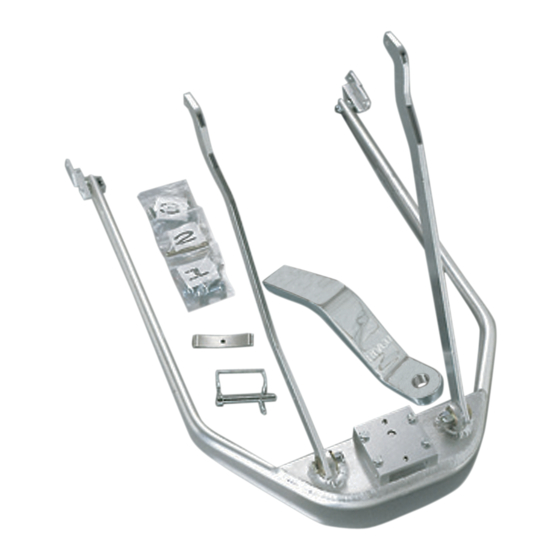
Read through these instructions completely before attempting installation, and lay out all pieces
including the numbered hardware bags to familiarize yourself with all parts - see photo #1.
1. Place the motorcycle on its centerstand; remove the seat (four 6mm Allen screws securing the grab handles to
the seat), painted side covers (this will require opening the saddlebag lids), and gray plastic frame covers
surrounding the rear crash bars and passenger floorboards (three 5mm Allen screws on each). Remove the rear
fender by first removing the four 5mm Allen screws as shown in photo (2A).
2. Remove the rear crash bars and lower sub-frames (photos 3 A & B) mounting bolts. Next - drill out the
threads of the sub-frame mounting bolt hole on the right side
required due to the limited space between the hitch and rear suspension.) The new bolt supplied for this hole is
longer and will now screw into the threaded hole on the right side of the hitch's frame.
3. Install the right frame reinforcement plate (item 1F). Referring to photo (#3), start two of the M8 x 25mm
bolts from bag #1 into the upper holes
plate (photo 1G) using the two remaining M8 x 25mm bolts from bag #1 in the upper holes - again start just a
few threads, do not tighten. Install the longer of the two remaining bolts from bag #1 (M8 x 50mm) in the
lower hole on the left side, and tighten this bolt securely (26-28 ft lbs.). The remaining shorter bolt will be
installed on the right side later.
4. Referring to photo (4A) remove the upper sub-frame from mainframe mounting bolts. Referring to photo (4B)
unplug all of the small wires that run under the end of the black sub frame and re-route them around the
outside of the sub
frame,
This will make more room for the struts that will be installed in the next step.
5. Install the left and right struts (photo 1 items B and C), they are marked "left inner" and "right inner" by
sliding them up from below between the inner fender and saddlebag, starting in a nearly vertical position. (See
photo #5). The right side will be more difficult and require some twisting" to get them into position. Take care
not to pinch or cut any of the wire looms near the mounting holes. It will help to have another person guide the
strut from the top and tell you how to maneuver it for it to slide up into place. Once in place install the 5/16" X
2 ¼" long bolts, washers, and nuts from bag #2 through the frame, sub-frame, and struts. Snug only - do not
tighten. Angle the bottom of the struts to the rear as far as possible and move the rubber drain hose near the
rear of the left strut around to the other side of the strut. Locate the heat shield on top of the right muffler (this
is to keep the rear brake caliper cooler). Remove the 10mm acorn nut at the rear of the heat shield and replace
it with the regular 10mm nut supplied.
6. Install the hitch main frame (photo (1), item A) as shown in photo (6) by placing it around the rear wheel and
below the mufflers. Angle the right side up and over the right muffler. As shown in photo (7), push the left
side up over the left muffler. Note: this will require some force and slight flexing of mufflers. Slide the left
side of the hitch over the end of the M8 x 50mm bolt installed earlier in step #3. Locate the remaining M8 x
40mm bolt from bag #1. Apply a small amount of Loc-Tite or similar thread locking compound (not included)
to the bolt. Align the right side of the hitch and install the bolt as shown in photo (3B), threading it into the
hole of the hitch - then tighten securely (26-28 ft lbs.). Install the 8mm nut from bag #1 on the left side and
tighten to (20-22 ft lbs.) while holding the bolt head with a wrench. Remove the 8mm x25mm bolts started
earlier and install the rear crash bars using these longer bolts and tighten securely (26-28 ft lbs.). Reinstall the
gray plastic frame covers.
#GL18007-30
-
just a few threads, do not tighten. Install the left frame reinforcement
then back thru the holes in the silver main frame (photo 4C) and reconnect them.
ONLY
(photo 3B) using a 5/16" drill. (This is
Advertisement
Table of Contents

Related Manuals for Rivco GL18007-30

Summary of Contents for Rivco GL18007-30
- Page 1 2012 & NEWER GL1800 TRAILER HITCH INSTALLATION INSTRUCTIONS #GL18007-30 Read through these instructions completely before attempting installation, and lay out all pieces including the numbered hardware bags to familiarize yourself with all parts - see photo #1. 1. Place the motorcycle on its centerstand; remove the seat (four 6mm Allen screws securing the grab handles to the seat), painted side covers (this will require opening the saddlebag lids), and gray plastic frame covers surrounding the rear crash bars and passenger floorboards (three 5mm Allen screws on each).
- Page 2 NOTE: Unless you have all LED lighting on your trailer it is STRONGLY recommended to use an electronic trailer wiring isolator (not supplied) RIVCO pt# GL18007-IU. It is designed to draw the additional 7-10 amps of power needed for the trailer’s lighting directly from the battery, not thru the brake, tail or turn signal circuits of the motorcycle.
- Page 3 They can also be purchased at most auto parts stores but will not have our plug in connector and will need to be spliced in line. You will also need our plug in wiring sub harness Rivco pt# GL18007-38 to connect the motorcycles wiring to the isolator and or the 5 to 4 wire convertor.
- Page 4 20. Using a test light or meter turn on the ignition and test the tail, brake and turn signal functions at the appropriate colored wires at the end of the isolator harness where you will be attaching your trailer plug. Connect your trailer plug to the harness to obtain the correct light functions.
- Page 5 IMPORTANT: AS A SAFETY PRECAUTION CHECK THE FOLLOWING BEFORE EVERY TRIP: Visual Inspection of Hitch and Mounting Bolts. *Safety Chains are Attached Properly. *Trailer Lights Function Properly. *Hitch Pin on & Clipped. *Check Air Pressure In Trailer Tires. Thank you for purchasing a RIVCO Product!
- Page 8 GL18007-38 (2012 & UP HONDA GL1800 GOLDWING) ISOLATOR WIRING DIAGRAM 3-PIN CONNECTOR (UNDER SEAT) BLUE (R TURN) ORANGE (L TURN) BLACK MODULE BROWN (TAIL) GREEN (STOP) 2-PIN CONNECTOR (INSIDE TRUNK LID) BROWN/WHITE BROWN/WHITE BIKE GREEN GREEN BLUE BLUE GREEN (TAIL) ISOLATOR BLUE (STOP) 4-PIN PLUG...
Need help?
Do you have a question about the GL18007-30 and is the answer not in the manual?
Questions and answers