
Related Manuals for Limotec MD300


Summary of Contents for Limotec MD300
- Page 1 USER MANUAL MD300 fire detection control panel Short guide for the user 01-11-2012 LIMOTEC bvba Bosstraat 21 B – 8570 Vichte Tel +32 (0) 56 650 660 www.limotec.be HG0300E02D...
-
Page 2: Table Of Contents
1 TABLE OF CONTENTS STANDARDS AND CERTIFICATION ....................3 DESCRIPTION OF THE MD300 CONTROL PANEL ................3 THE OPERATOR CONSOLE OF MD300 CONTROL PANEL ..............4 AN OVERVIEW ......................... 4 DESCRIPTION ........................... 5 4.2.1 LCD WITH TOUCH SCREEN ....................5 4.2.2... -
Page 3: Standards And Certification
The MD300 non-modular control panel is equipped with 16 detector loops as standard. The MD300 control panel is equipped with a serial Input/output bus as standard, to which up to 8 repeater panels and 8 extension relay cards can be connected. -
Page 4: The Operator Console Of Md300 Control Panel
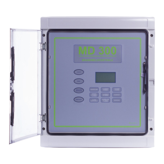
4 THE OPERATOR CONSOLE OF MD300 CONTROL PANEL 4.1 AN OVERVIEW LCD touch screen Visual indications Control buttons HG0300E02D... -
Page 5: Description
The LCD of the MD300 control panel is equipped with a background LED light, which lights up every time the screen is touched or a control button is pressed and every time there is a new fire alarm or fault message on the system. -
Page 6: The Pilot Screen
The pilot screen appears as soon as the control panel is at rest (there are no fire alarm or fault messages on the system). The text “MD300 (control panel)” is the default control panel name. This name can be changed at the user’s request during system commissioning. All the other texts, on the other hand, cannot be adapted. - Page 7 The fire alarms of a loop placed “in test” are only indicated on the display of the MD300 control panel and do not activate the built-in buzzer of the control panel or the repeater panels. The output controls for warning and evacuation are placed completely “out of service”.
-
Page 8: The Event Screen
These detector loops have the same authority as the control button “EVACUATION” on the front of the MD300 control panel. « OPEN »: technical fault caused by an interruption in the wiring of the loop or by the removal of a fire detector from its base. - Page 9 AN OVERVIEW OF THE TYPE OF MESSAGES: POWER SUPPLY FAULTS: the MD300 fire detection control panel is connected to the 230Vac mains voltage. In the event of a power failure, the built-in batteries automatically take over the operation of the control panel.
- Page 10 TECHNICAL FAULTS RELATING TO THE INTERNAL MONITORING OF THE MD300 CONTROL PANEL: « EXTERNAL CONTROLLER »: the main processor of the MD300 control panel is monitored by an external processor. In case of failure of the main processor, the external processor will signal this with the LED “SYSTEM FAILURE”.
- Page 11 The second text line indicates the type and address of the peripheral module that caused the message. A peripheral module is an external module that is connected to the MD300 I/O bus. There are 3 types of peripheral modules: repeater panels, extension relay cards and power supply monitors (internally installed in each control panel).
- Page 12 B. COMMUNICATION ERRORS: COMM.ERROR Relay card 1 COMM.ERROR Relay card 1 PREVIOUS NEXT Sequence number of the message Number of the relay card Scroll buttons Common message “COMM.ERROR” The first line of text shall include the test “COMM. ERROR” and the sequence number of the message.
- Page 13 The first line of text shall include the test “PAR. ERROR” and the sequence number of the message. The second text line indicates the nature of the parameter error that caused the message. A parameter error signals a problem in setting the parameters of the MD300 fire detection control panel.
-
Page 14: The Menu Screen
THE MENU SCREEN In addition to the basic functions buttons « SILENCE », « RESET », « EVACUATION DELAYED » and « EVACUATION », the MD300 control panel can also be operated via a menu structure. 13 October 09 10 : 15... - Page 15 Entering a digit of the access code is suggested by “*”. If an incorrect code is entered, the system returns to the pilot screen. When entering a correct code, the system also returns to the pilot screen, but the function button “OPERATION” is colored black. The MD300 control panel is now in operating level 2.
- Page 16 All basic function buttons of the MD300 control panel are now available. The buttons “RESET” and “EVACUATION” are indicated by a white background LED lighting. The following menu functions can be performed using the function button “MENU” on the pilot screen: «...
-
Page 17: The Basic Function Buttons
4.3 THE BASIC FUNCTION BUTTONS All basic function buttons of the MD300 control panel are equipped with a background LED lighting. The function buttons “SILENCE” and “DELAYED EVACUATION” are equipped with a yellow background LED lighting. The “RESET” and “EVACUATION” function buttons are equipped with a white background LED lighting. -
Page 18: Function Button "Evacuation
4.3.4 FUNCTION BUTTON “EVACUATION” The function button “EVACUATION” is only available in operating level 2. The availability of this button is indicated by a white background LED lighting. After pressing the button “EVACUATION”, a confirmation will be requested on the LCD. -
Page 19: The Visual Indications
4.4 THE VISUAL INDICATIONS Red LED « FIRE ALARM »: lights up in case of an alarm message on one or more detector loops. Yellow LED « COMMON FAULT »: lights up in the event of a technical failure (fault in the detector loop, fault in a siren circuit or power supply failure). -
Page 20: Signalling Warning - Evacuation
MD300 control panel has not been accepted (accept = operate the “SILENCE” button). Either after the set evacuation-intervention time has elapsed (see below) if the alarm message has not yet been reset on the MD300 control panel. The alarm message is reset as follows: ... -
Page 21: Functioning In The Event Of An Alarm Message With The Control Panel In Delayed Mode Of Operation
6 FUNCTIONING IN THE EVENT OF AN ALARM MESSAGE WITH THE CONTROL PANEL IN DELAYED MODE OF OPERATION THE YELLOW LED “EVACUATION DELAYED” IS ILLUMINATED ! A fire alarm message is triggered in the following cases: An optical, a multi sensor or a linear detector detects smoke... - Page 22 Press a text area (grey area on the event screen) on the LCD to select the pilot screen 13 October 09 10 : 15 _________________________ MD300 control panel SYSTEM IN USE OPERATION MENU Use the function button “OPERATION” to select the screen for entering the access code * .
- Page 23 FIRE ? ↓ YES: EXECUTE THE EVACUATION PLAN! ↓ Start the evacuation sirens by pressing the function button “EVACUATION” (if necessary, place the MD300 control panel in operating level 2) Press “YES” on the LCD to activate the evacuation sirens HG0300E02D...
- Page 24 ! ↓ RESET THE MD300 CONTROL PANEL (control panel in operating level 2) Press a text area (grey area on the event screen) on the LCD to select the pilot screen Use the function button “OPERATION” to select the screen for entering the access code Enter the access code (factory access code = ‘1’...
-
Page 25: Functioning In The Event Of An Alarm Message With The Control Panel In Direct Mode Of Operation
7 FUNCTIONING IN THE EVENT OF AN ALARM MESSAGE WITH THE CONTROL PANEL IN DIRECT MODE OF OPERATION THE YELLOW LED “EVACUATION DELAYED” IS NOT ILLUMINATED ! A fire alarm message is triggered in the following cases: An optical, a multi sensor or a linear detector detects smoke... - Page 26 Press a text area (grey area on the event screen) on the LCD to select the pilot screen 13 October 09 10 : 15 _________________________ MD300 control panel SYSTEM IN USE OPERATION MENU Use the function button “OPERATION” to select the screen for entering the access code * .
- Page 27 ↓ YES: EXECUTE THE EVACUATION PLAN! ↓ Restart the evacuation sirens by pressing the function button “EVACUATION” (if necessary, place the MD300 control panel in operating level 2) Press “YES” on the LCD to activate the evacuation sirens ↓ ↓...
-
Page 28: Evacuation Of The Building
8 EVACUATION OF THE BUILDING Press the LCD until the pilot screen is displayed 13 October 09 10 : 15 _________________________ MD300 control panel SYSTEM IN USE OPERATION MENU ↓ Press the function button “EVACUATION” Use the function key “OPERATION” to select the screen for entering the access code if operating level 2 is not yet active and enter the access code (factory access code = ‘1’... -
Page 29: Functioning In Case Of A Fault Message
The yellow LED “TRANSMISSION OFF SERVICE/FAULT” lights up in case of an error in the cabling to the telephone transmitter. The yellow LED “SYSTEM FAILURE” lights up in case of an internal fault in the MD300 control panel. Operation of the control panel in the event of a fault message: FAULT MESSAGE ↓... - Page 30 ! ↓ RESET THE MD300 CONTROL PANEL (control panel in operating level 2): Press a text area (grey area on the event screen) on the LCD to select the pilot screen. 13 October 09...
-
Page 31: Operating The Md300 Control Panel
10 OPERATING THE MD300 CONTROL PANEL Depending on the active operating level (level 1 or level 2) and by means of the function button “MENU”, an operating menu can be displayed on the pilot screen. 10.1 OPERATING LEVEL 1 Operating level 1 = the function button “OPERATION”... -
Page 32: To Switch On/Off A Detection Loop
All connected fire detectors are completely isolated and can therefore not cause any messages. The loops that are not switched off remain in normal operation. 1. Place the MD300 control panel in operating level 2 and use the function button “MENU” to select the main menu of level 2. - Page 33 3. Use the function button “SWITCH ON/OFF” to select the submenu for switching on/off a detector loop, the warning and evacuation sounders or the output to the telephone transmitter. SWITCH ON/OFF LOOP SIREN TRANSMIT ↓ 4. Use the function button “LOOP” to select the submenu for switching on/off a detector loop.
- Page 34 8. The pilot screen displays the detector loop that has been switched off. If several detector loops are out of service, they are placed on the screen in a scroll cycle of 5 seconds. 13 October 09 10 : 15 _________________________ MD300 control panel OUT OF SERVICE 1. Loop 1 OPERATION MENU...
- Page 35 8570 Vichte DOP-MD300-2013 - EN54-2 : 1997/A1 : 2006 - EN54-4 : 1997/A1 : 2002/A2 : 2006 MD300 MD300: Conventional 16-loop fire detection control panel. Designed for use in fire alarm installations in and around buildings. Essential characteristics Achievements General requirements...
Need help?
Do you have a question about the MD300 and is the answer not in the manual?
Questions and answers