Advertisement
Additional Information
3
UL Compliance Notes:
1). For UL1076 Proprietary Burglar Alarm Systems and Non-Stand Alone UL294 Access Control System (central monitoring
employed) installations, Altronix AL400ULX power supply must be used for system battery supervision function.
2). When using Altronix AL400ULX power supply, the installer will need to provide a remote input to the AC24/4 to monitor AC
power loss and battery supervision conditions as indicated below:
Altronix AL400ULX
I/O Board at
Power Supply
DB/DBU Location
C
+
AC Fail
Monitor
Monitoring
-
Point 1
NO
Relay
NC
+
10K Ohm
C
-
Battery
NO
Monitoring
Relay
NC
10K Ohm
12 VDC Out
+
-
7000-0126
Black
-
Black
+
Black
12 VDC to power Local
Red
boards & devices
3). For UL294 Stand-Alone Installations, the MN-TRANS-75-UL and MN-PSU-KIT-MKII can be employed.
9600-0492
. AC24/4 Alarms Controller Installation Instructions, Issue 1.2.1x1 12th December 2013. © G4S
Technology 2013. G4S Technology Limited cannot be held liable for technical and editorial omissions or errors
made herein; nor for incidental or consequential damages resulting from the furnishing, performance or use of
this material. All trademarks acknowledged.
NOTE: This equipment has been tested and found to comply with the limits for a Class A digital device,
pursuant to part 15 of the FCC Rules. These limits are designed to provide reasonable protection against
harmful interference when the equipment is operated in a commercial environment. This equipment generates,
uses and can radiate radio frequency energy and, if not installed and used in accordance with the instructions,
may cause harmful interference to radio communications. Operation of this equipment in a residential area is
likely to cause harmful interference. In which case, the user will be required to correct the interference at his
own expense.
Program Monitor Point 1 as 3
State N.C., and program the
Monitor Point Message to read
"AC Power Fail, (Add Board
Description)"
Monitor
Program Monitor Point 2 as 3
Point 2
State N.C., and Alarm Message
should read "Battery Trouble,
(Add Board Description)"
Cabinet
AC Power /
Tamper Board
Specifications
Monitor points: 24 max.
Auxiliary outputs: 4 max.
Quiescent supply input: 75mA @12Vdc (no relays
energized).
Maximum supply input: 195mA @12Vdc (all relays
energized). Each relay consumes 30mA when energized.
Operating Range: 14 to 131°F (-10 to 55°C) max.
Humidity 15 to 90% non-condensing; indoor use only.
Compliance: EN50133, 1999/5/EC, UL 294 Access
Control & UL1076 Proprietary Burglar Alarm Systems.
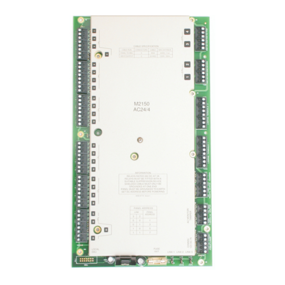
M2150 AC24/4 Alarms Controller Installation Instructions
The AC24/4 alarms controller is a remote alarms control unit for M2150
security management systems. The controller enables direct
connection of up to 24 monitor points (for alarms monitoring) and 4
auxiliary outputs, and can be sited up to 3000ft (1km) from the
controlling M2150 DBU, 2DBC, 4DBC or 8DBC database unit (some of
these database units are available only in selected countries).
Note:
For additional information regarding the installation, configuration
and proper use of this product:
SMS User Guide, P/N 9600-0429
M2150 Access Control Design Guide, P/N 9600-0420
M2150 Intrusion Guide, P/N 9600-0540.
M2150 UL1076 Compliance Manual, P/N 9600-0449.
Some devices described in these instructions may not be
applicable for sites requiring UL compliance. Please refer to the
Access Control Design Guide for details of the controllers, modules
and features that have been UL tested for use with this device.
Note: For information on mounting the alarms controller into the
cabinet, refer to the appropriate cabinet installation instructions.
Addressing
1
Set the address of the controller using the links shown below. When connected to a DBU, the controller can be set to address
1, 3, 5 or 7. When connected to a 2DBC or 4DBC, the controller must be set to address 3, 5 or 7. When connected to an
8DBC, the controller must be set to address 5 or 7. An alarms controller occupies two addresses (e.g. 5 and 6).
Position 1
Link Positions
Address
ADR0
ADR1
ADR0 (LK2)
1
0 (OFF)
0 (OFF)
3
1 (ON)
0 (OFF)
5
0 (OFF) 1 (ON)
7
1 (ON)
1 (ON)
ADR1 (LK3)
Position 0
(OFF)
Replacement Parts:
Use only replacement parts provided by the manufacturer:
F1, P/N R-0811-1000
(ON)
Alarms Controller
Advertisement
Table of Contents

Related Manuals for G4S M2150

Summary of Contents for G4S M2150
- Page 1 9600-0492 . AC24/4 Alarms Controller Installation Instructions, Issue 1.2.1x1 12th December 2013. © G4S Technology 2013. G4S Technology Limited cannot be held liable for technical and editorial omissions or errors Monitor points: 24 max. made herein; nor for incidental or consequential damages resulting from the furnishing, performance or use of Auxiliary outputs: 4 max.
- Page 2 7). Some devices described in these instructions may not be applicable for sites requiring UL compliance. Please refer to the M2150 Access Control Design Guide for details of the controllers, modules and features that have been UL tested for use with...
Need help?
Do you have a question about the M2150 and is the answer not in the manual?
Questions and answers