Cascade TEK TVO-2 Installation And Operation Manual
Vacuum ovens
Hide thumbs
Also See for TVO-2:
- Instruction manual (16 pages) ,
- Installation and operation manual (66 pages)
Table of Contents
Advertisement
Advertisement
Table of Contents

Related Manuals for Cascade TEK TVO-2


Summary of Contents for Cascade TEK TVO-2
- Page 1 Vacuum Ovens TVO-2 TVO-5 Installation and Operation Manual...
- Page 2 Pictured on front cover, left to right: TVO-2, TVO-5 Manufacturing Warranty For warranty information outside the USA please visit: www.cascadetek.com/resource/limited-international-warranty-policy-cascade-tek-solution-llc For warranty information inside the USA please visit: www.cascadetek.com/resource/limited-usa-warranty-policy-–-cascade-tek-solutions-llc P a g e...
- Page 3 TVO-5 CTV222 CTV522 Cascade TEK is a brand of Sheldon Manufacturing, INC. Safety Certifications These units are CUE listed by TÜV SÜD as vacuum ovens for professional, industrial or educational use where the preparation or testing of materials is done at an ambient air pressure range of 22.14 –...
-
Page 4: Table Of Contents
TABLE OF CONTENTS INTRODUCTION ................................. 7 Read this Manual ..................................7 Safety Considerations and Requirements ........................7 Contacting Assistance ................................8 Engineering Improvements..............................8 Vacuum Supply Required ..............................9 Gaskets ....................................10 RECEIVING YOUR OVEN ............................11 Inspect the Shipment ................................11 Orientation Photos ................................ - Page 5 Power ...................................... 58 REPLACEMENT PARTS LIST..........................59 Replacement Gaskets ................................ 60 P a g e...
- Page 6 TABLE OF CONTENTS P a g e...
-
Page 7: Introduction
INTRODUCTION Thank you for purchasing a Cascade TEK oven. We know you have many choices in today’s competitive marketplace when it comes to constant temperature equipment. We appreciate you choosing ours. We stand behind our products and will be here if you need us. -
Page 8: Contacting Assistance
Therefore, some changes, modifications, and improvements may not be covered in this manual. If your unit’s operating characteristics or appearance differs from those described in this manual, please contact your Cascade TEK dealer or customer service representative for assistance. -
Page 9: Vacuum Supply Required
5 cfm 142 Liters per Minute Cascade TEK recommends evacuating the oven to 500 torr as part of the first step in a baking recipe to verify the oven is sealed. This helps safeguard the oven and pump. P a g e... -
Page 10: Gaskets
INTRODUCTION ASKETS Gaskets are non-warranty, high-wear consumable items subject to compression forces, heat, and outgassed byproducts. Heavy usage rates may necessitate frequent replacements. The manufacturer strongly recommends keeping a spare gasket on hand during operation. Each oven comes with a replaceable silicone gasket installed on the chamber liner. This gasket seals against the chamber door to maintain the vacuum integrity of the chamber. -
Page 11: Receiving Your Oven
5. The unit should come with an Installation and Operation Manual and a profile programming guide. 6. Verify the correct number of accessories has been included. Carefully check all packaging for accessories before discarding. Included Accessories: TVO-2 Tall Shelves Short Bottom Shelf Power Cord Leveling Feet... -
Page 12: Orientation Photos
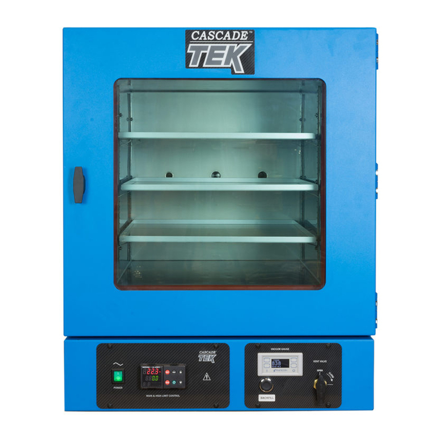
RECEIVING YOUR OVEN RIENTATION HOTOS Back of Unit: Vacuum Port, Vent Port, Data Ports (See page 14) Figure 1: TVO-5 Shelf Standard Rail Chamber Door Access Port (KF-25 Fitting) Chamber Gasket Seal Temperature Sensor Probe Oven Chamber Main Control Panel Vacuum Control Panel and Display 12 | P a g e... - Page 13 RECEIVING YOUR OVEN Figure 2: TVO-2 Tall Shelf Back of Unit: Vacuum Port, Vent Port, Data Ports Tall Shelf Chamber Door Short Shelf (Bottom) Chamber Gasket Seal Main Control Panel Vacuum Control Access Port Panel and Display (KF-25 Fitting) 13 |...
- Page 14 RECEIVING YOUR OVEN Back of Ovens KF-25 Vacuum Port (Includes Blank and Clamp, not pictured here) Vacuum Port, 3/8 inch (9.52 mm) Chamber Vent Inlet Port ¼ inch (6.35 mm) Data Plate Power Cord Inlet 9-Pin Voltage Output Port RS485 Data Port - 25 Pin Fuse Holder 14 | P a g e...
-
Page 15: Record The Data Plate Information
RECEIVING YOUR OVEN ECORD THE LATE NFORMATION The data plate contains the unit model number, serial number, part number, and part ID. Tech Support will need this information during any support call. Record it below for future reference. The data plate is located on the back of the oven above the power inlet. •... - Page 16 RECEIVING YOUR OVEN 16 | P a g e...
-
Page 17: Installation
INSTALLATION NSTALLATION ROCEDURE HECKLIST For installing the oven in a new workspace location. Pre-Installation Verify that a vacuum supply source suitable for your application is available and can be connected to the oven, page 9. See page 23 for the oven gas and vacuum port locations. •... -
Page 18: Required Ambient Conditions
6” (152 mm) 6” (152 mm) Door Swing TVO-2: 20.5” (521 mm) TVO-5: 27.0” (686 mm) 6 inches (152 mm) of clearance is required on the sides. 12 inches (305 mm) of headspace clearance is required between the top of the unit and any overhead partitions. -
Page 19: Power Source Requirements
Power Source: The wall power outlet must meet the power requirements listed on the unit data plate. Model AC Voltage Amperage Frequency Standard 15- 110 – 120 10.0 50/60 Hz TVO-2 amp NEMA 5-15 power 110 – 120 13.0 50/60 Hz TVO-5 outlet. Wall power sources must be protective earth grounded and single phase. •... -
Page 20: Leveling
INSTALLATION EVELING The unit must be level and stable for safe operation. Install the 4 leveling feet in the 4 corner holes in the bottom of the oven. To prevent damage when moving the unit, turn all 4 leveling feet so that the leg of each foot Note: sits inside the unit. -
Page 21: Shelving Installation
Never place samples or product on the oven chamber floor. The floor runs hotter than the shelf temperatures. All oven heating specifications are for shelving temperatures only. TVO-2 Temperature Probe Shelf Clip Bottom of Short Shelf Carefully slide the short shelf into position on the chamber floor, sliding the clip on the bottom of the shelf onto the oven temperature probe. - Page 22 INSTALLATION Shelving Installation Continued TVO-5 Shelving To ensure accurate temperature measurement, one shelf bottom must be in close proximity to the oven temperature probe. This probe extends out from the chamber back wall. Do not place the shelf in direct contact with the probe. Shelf Probe Install 4 Shelf Clips...
-
Page 23: Connect To The Vacuum Supply
INSTALLATION ONNECT TO THE ACUUM UPPLY Use clamps to secure tubing to the Vacuum and Vent Ports. KF-25 Vacuum Port 1. Vacuum Supply: Connect to the 3/8 inch (9.52mm) Vacuum Port. Optional: Connect a clean gas supply to the Vent Port (Backfill Inlet). - Page 24 INSTALLATION 24 | P a g e...
-
Page 25: Graphic Symbols
GRAPHIC SYMBOLS The oven is provided with multiple graphic symbols on its interior and exterior surfaces. The symbols identify hazards and the functions of the adjustable components, as well as important notes in the operation manual. Symbol Definition Consult the operation manual Consulter le manuel d'utilisation Over Temperature Limit system Thermostat température limite contrôle haute... - Page 26 GRAPHIC SYMBOLS 26 | P a g e...
-
Page 27: Control Overview
CONTROL OVERVIEW Control Panels Power Switch The switch illuminates when in the ON ( I ) position. Temperature Controller - Display on Homepage Top Line (Red): Present chamber shelving temperature Middle Line (Green): The constant temperature setpoint Bottom Line: Flashing “2” indicates active heating While on the homepage, the Up and Down arrow buttons adjust the constant temperature setpoint. - Page 28 CONTROL OVERVIEW Vacuum Gauge As set at the factory, this gauge shows the chamber vacuum level relative to sea level atmospheric pressure in inches of mercury (inHg). The display range is 0 to -29.9inHg. Zero is the room atmosphere pressure at sea level and -29.9inHg a near-perfect vacuum. See page 39 for how to display other units of measurement or zero the gauge to your local altitude.
-
Page 29: Operation
OPERATION Safe operation of the oven is dependent on the actions and behavior of the oven operators. Operating personnel must read and understand the Operating Precautions in this section prior to operating the oven. The operators must follow these instructions to prevent injuries and to safeguard their health, environment, and the materials being treated in the oven, as well as to prevent damage to the oven. -
Page 30: Theory Of Operation
OPERATION HEORY OF PERATION Vacuum Vacuum is supplied by an external vacuum supply (a pump or building system) connected to the vacuum port on the back of the oven. Vacuum levels obtained in the oven chamber are dependent on pump type and performance, valve settings, and the nature of the application or process, including the volume of materials outgassed. - Page 31 OPERATION Heating Control The oven temperature controller stores an operator-selected constant temperature setpoint. When powered, the oven heats the chamber shelves to the setpoint. The controller board is wired to a solid-state temperature probe located in the chamber on the rear wall. When the controller detects that the shelf temperature has dropped below the temperature setpoint, it pulses power to the heating elements.
-
Page 32: Put The Oven Into Operation
VENT OPERATION UT THE VEN INTO PERATION Verify all of the required procedures in the Installation section have been carried out. Then perform the following steps and procedures to prepare the oven for use in a new location. Attach the Power Cord Attach the power cord that came with the unit to the power inlet receptacle on the back of the oven. - Page 33 OPERATION Continued from the previous page Verify Vacuum Integrity Place the Chamber Under Vacuum for a minimum of 10 minutes to verify the integrity of the vacuum supply system. See page 35. 10 Minutes Minimum Set the Operating Temperature • Set the constant temperature setpoint.
-
Page 34: Set The High Temperature Limit
OPERATION ET THE EMPERATURE IMIT Note: Test the high limit system once per year for functionality. The high temperature limit is set by the operator at least 10°C above the highest temperature the oven will run at during your baking application. Advance to the Limit High Setpoint, starting on the homepage Push the Advance button repeatedly until “Lh.S1”... -
Page 35: Evacuating And Backfilling The Oven Chamber
OPERATION VACUATING AND ACKFILLING THE HAMBER Put the oven chamber under vacuum and hold for at least 10 minutes when first putting the oven into operation in a new location to verify the integrity of the vacuum supply system. The oven chamber must be drawn down to at least -3inHg (-76mmHg or -10kPa) in order to seal. -
Page 36: Setting The Constant Temperature Setpoint
OPERATION ETTING THE ONSTANT EMPERATURE ETPOINT Adjust the constant temperature setpoint on the homepage Stay 10°C below the high limit • setpoint. Note: Holding down an arrow button will cause the temperature to advance in increments of ten (10). Adjust Release the arrow buttons after adjusting the setpoint •... -
Page 37: High Temperature Limit Activated
OPERATION EMPERATURE IMIT CTIVATED The High Limit system cuts off heating in the oven whenever the chamber temperature meets or exceeds the Limit setting. Heating remains disabled until the oven operator clears the Limit cutoff. Indicators When heating is cut off, the oven display flashes two alternating alert screens. Alternating Alert Screens Additionally, an illuminated “4”... -
Page 38: Change Unit Of Measurement
OPERATION ⁰C ⁰F HANGE NIT OF EASUREMENT The controller can display temperatures in either Celsius or Fahrenheit. From the homepage, advance to the “C_F1” unit of measurement option. a. Push the green Advance button 7 times. 2. Change the unit of measurement. a. -
Page 39: Vacuum Gauge Operations
OPERATION ACUUM AUGE PERATIONS Change the Unit of Measurement Place the vacuum gauge in its adjustment mode. a. Press and hold the “M” button for approximately 3 seconds • The display will begin to blink and show a unit of measurement Inches of Mercury 2. -
Page 40: Maximum Obtainable Vacuum
OPERATION AXIMUM BTAINABLE ACUUM The maximum obtainable vacuum is determined by the altitude of the oven workspace or laboratory environment. The atmosphere is less dense at higher altitudes than at sea level. While a vacuum pump will evacuate the same percentage of atmosphere from the oven chamber, less overall pressure is expelled because of the reduced density. -
Page 41: Data Ports
OPERATION ORTS 25-Pin Port The RS485 data port, located on the back of the oven, connects to the oven temperature controller. The port is primarily intended for updating the controller software but can be used for data logging and graphical profile programming. Accessing the controller with a computer requires a 25-pin RS485-to-USB converter cable and driver software. - Page 42 OPERATION 42 | P a g e...
-
Page 43: Operator Maintenance
OPERATOR MAINTENANCE Warning: Disconnect the unit from its power supply prior to maintenance or cleaning of this unit. Avertissement: Avant d'effectuer toute maintenance ou entretien de cet appareil, débrancher le cordon secteur de la source d'alimentation. LEANING If a hazardous material or substance has spilled in the unit, immediately initiate your site Hazardous Material Spill Containment protocol. -
Page 44: Maintaining Atmospheric Integrity
OPERATOR MAINTENANCE AINTAINING TMOSPHERIC NTEGRITY Periodically, inspect the door latch, trim, catch, and gasket for signs of deterioration. Failure to maintain the integrity of the door system shortens the lifespan of the unit. The gasket should be replaced if it is dry, cracked, or otherwise showing a loss of elasticity. LECTRICAL OMPONENTS Electrical components do not require maintenance. -
Page 45: Diagnostic Questionnaire - Heating Issues
OPERATOR MAINTENANCE — H IAGNOSTIC UESTIONNAIRE EATING SSUES If the unit is experiencing heating issues, use this questionnaire to gather information on the unit prior to contacting Technical Support. Gathering and sharing this information aids Tech Support in making timely and accurate remote diagnosis. - Page 46 OPERATOR MAINTENANCE Does the car actually have gas in the tank? Have you physically verified the computer is Note: plugged in? Yes, we are going ask some very basic questions. Please bear with us. Methodical verifications and the elimination of potential causes of failure are often the quickest means of getting a unit back into operation.
- Page 47 OPERATOR MAINTENANCE Optional: Obtain a temperature reference device. A calibrated digital thermometer with a vacuum- rated thermocouple feedthrough. The device must be accurate to at least 0.1°C. Diagnostic Setup The unit must be connected to a power source that meets the requirements in the Installation chapter (page 19) and turned on.
- Page 48 OPERATOR MAINTENANCE SDRAP Diagnostic Questions Record the answers in the log on page 49. etpoint? What is the current temperature setpoint? Chamber Temperature in Red Setpoint in Green isplay? What chamber temperature is presently showing on the temperature display? eference? Optional: What temperature is the reference device presently showing for the chamber temperature? mbient?
- Page 49 OPERATOR MAINTENANCE SDRAP Answer Log Record answers to the SDRAP questions in this log. These document the unit behavior. SDRAP Record SDRAP Answers and Any Notes Here etpoint, present setting: isplay, present Temperature reading: eference device, present reading: mbient, present temperature: Heating Indicator: ilot Lights, illuminating Y/N?
-
Page 50: Diagnostic Questionnaire - Vacuum Leak Issues
OPERATOR MAINTENANCE — V IAGNOSTIC UESTIONNAIRE ACUUM LEAK ISSUES If the unit is experiencing heating issues, use this questionnaire to gather information on the unit prior to contacting Technical Support. Gathering and sharing this information aids Tech Support in making timely and accurate remote diagnosis. - Page 51 OPERATOR MAINTENANCE Does the car actually have gas in the tank? Have you physically verified the computer is Note: plugged in? Yes, we are going ask some very basic questions. Please bear with us. Methodical verifications and the elimination of potential causes of failure are often the quickest means of getting a unit back into operation.
- Page 52 OPERATOR MAINTENANCE Diagnostic Setup Check the primary chamber gasket for damage. This is the gasket mounted either on the chamber liner or the door that seals the oven chamber when the door is closed. Look for: Cuts or nicks on the gasket caused by removing shelves or samples •...
- Page 53 OPERATOR MAINTENANCE Diagnostic Questions ump On and Running? Yes or no? ent Valve Closed? The vent (backfill inlet port) must be closed before applying vacuum to the chamber. Failure to do so may result in damage to your vacuum pump. acuum Valve Open? The vacuum valve must be open to allow a connected vacuum supply to evacuate the oven chamber.
- Page 54 OPERATOR MAINTENANCE eak Verification, Y/N? Verify that the oven is leaking and not experiencing outgassing from residual contamination. If the oven is hot, allow it to cool to room temperature. 2. Evacuate the chamber to the lowest achievable pressure. 3. Write down the pressure displayed on the Vacuum Gauge as a positive number. 4.
- Page 55 OPERATOR MAINTENANCE Vacuum Leak Diagnostic Data Log Record the diagnostic question answers in this log. These questions document the unit behavior. Diagnostic Questions Record Answers and Any Notes Here ump On and Running, Y/N? ent Valve Closed, Y/N? acuum Valve Open, Y/N? isplay Reading, Vacuum Gauge: erified the Oven is Leaking,...
- Page 56 OPERATOR MAINTENANCE 56 | P a g e...
-
Page 57: Unit Specifications
All indications are average values, typical for units produced in the series. We reserve the right to alter technical specifications at all times. EIGHT Model Unit Weight TVO-2 179.0 lb / 81.2 kg TVO-5 360.0 lb / 163.3 kg IMENSIONS... -
Page 58: Vacuum
Less than 1 mTorr per 30 minutes @ ambient temperature EMPERATURE Range, Stability, and Uniformity Model Range Stability Uniformity TVO-2 Ambient +20° to 220°C ± 0.2°C @ 150°C ±6% of Setpoint TVO-5 Ambient +20° to 220°C ± 0.25°C @ 150°C ±6% of Setpoint... - Page 59 REPLACEMENT PARTS LIST See the next page for gaskets Description Parts Number Description Parts Number Adjustable Leveling Shelf Short, TVO-2 Feet 9751226 2700506 Fuse, T16A 250V Shelf Clip, Individual (1), 5x20mm TVO-5 3300513 1250510 Power Cord 125 volt, Shelf, TVO-5 15Amp, 9ft 5 in (2.86m) NEMA 5-15P...
- Page 60 (457 x 457 mm) Ordering Parts and Consumables Parts may be ordered from Cascade TEK by calling 1-888-371-4096. Please have the model number and serial number of the unit ready, as Tech Support will need this information to match your oven with its correct part.
- Page 61 REPLACEMENT PARTS LIST 61 | P a g e...
- Page 62 Cascade TEK Solutions LLC P.O. Box 625 Bldg B Cornelius, Oregon 97113 support@cascadetek.com cascadetek.com 1-888-835-9250...
Need help?
Do you have a question about the TVO-2 and is the answer not in the manual?
Questions and answers