
Related Manuals for Edmunds TRENDSETTER

Summary of Contents for Edmunds TRENDSETTER
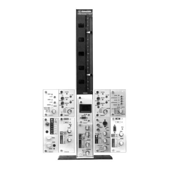
- Page 1 INSTRUCTION MANUAL Edmunds ™ TRENDSETTER EDMUNDS GAGES GAGES Edmunds FARMINGTON INDUSTRIAL PARK FARMINGTON, CT 06032 USA • (860) 677-2813 FAX (860) 677-4243...
- Page 2 TRENDSETTER™ Ever since it’s emergence in 1977, the Trendsetter™ gaging column has been the most reliable and technologically advanced column gage in the world. With both electric and air-to-electric capabili- ties, the Trendsetter™ is on the cutting edge of component and design technology while continuing to provide the user-friendly ease you’ve come to expect from all Edmunds products.
-
Page 3: Table Of Contents
2-2.1 Preparing For Use..................7 2-2.2 Setting the Air Reading................8 2-2.3 Mastering ..................... 9 2-2.4 Setting to Tooling other than Edmunds............. 10 3. Technical Description 3-1 E8000 Main Frame Assembly ................11 3-2 E8001 Limit Light Module 3 Point................ 14 3-3 E8007 Multipoint Classifying Module .............. -
Page 4: Electronic Gaging 2-1.1 Preparing For Use
EDMUNDS TRENDSETTER™ 2.1 ELECTRONIC GAGING 2-1.1 Preparing For Use - Electronic Gaging This opening description will be as brief as possible in an effort to minimize setup time. A more complete description of the column and it’s modules will be found later in the manual. To form a firm three point support for the column, unscrew the front screw at the bottom of the long foot and remount the foot on the front screw. -
Page 5: 2-1.2 Operation With Lvdt Cartridges
A, B, and AB. In some cases, where transducers other than Edmunds’ gage probes are being used, or where levers change the 1:1 ratio of input to output, the rear adjustments on the circuit board may need to... -
Page 6: 2-1.5 Main Mag Adjustment
Mount the A and B probes in the balancing fixture. Adjust each probe to its mechanical zero as observed on the Trendsetter™ bargraph display. Then with the range switch set to desired appli- cation range, and the polarity/function switches set to A+B mode, rotate the micrometer head some convenient distance. -
Page 7: 2.2 Air/Electronic Gaging
Trendsetter™ display to zero, push the master in a direction which is parallel to the plane that the gage probes are mounted in. The Trendsetter™ readout should remain fixed at zero. -
Page 8: 2-2.2 Setting The Air Reading
3.) Select the proper headers and reinsert the module. All Edmunds air tooling is marked with the full scale range for which it is intended to operate. Since overall range of air gaging is limited, the tooling is designed to operate on one scale only. -
Page 9: 2-2.3 Mastering
Unauthorized switching of ranges may affect the performance and linearity of the tooling. The tool- ing should be used with the following magnifications: Marked Range Air Amplification .010” /0.2mm .005” /0.1mm .002” / .05mm .001” / .02mm Med/High .0005”/ .01mm High To set the range of the module on the bargraph, turn the front panel range switch to required posi- tion using a small screwdriver inserted thru the front panel. -
Page 10: 2-2.4 Setting To Tooling Other Than Edmunds
Flow system tooling, which has a very shallow nozzle drop, will show very high magnification when used on a Trendsetter™. This might necessitate a change to a lower air amplification on the 3 range pin header. Differential type tooling will show a slightly lower magnification than the restriction bleed tooling, and may possibly require a high air amplification setting. -
Page 11: E8000 Main Frame Assembly
3-1 Functional Description - Rev. D. The E8000 Main Frame Assembly is the focal point for the various plug in modules associated with the Trendsetter™ system. The Main Frame provides mechanical support, interface wiring, I/O connections, power supplies and a bargraph readout.The Main Frame mea- sures 21.25”... - Page 12 CAUTION! OBSERVE HIGH VOLTAGES PRESENT WITHIN TRENDSETTER™ CABINET Main Frame Calibration Calibration consists of furnishing a +/- 2.500 volt input to the display card, and adjusting the gain pot. Before attempting, remove all plug-in modules, and observe all high voltage safety precau- tions.
- Page 13 The Common Buss On an application that requires the output of a measuring head to be fed into more than one col- umn for adding, averaging, checking clearance, etc., the output signal from the column is fed into a common buss wired to the 25 pin I/O connectors. A 25 pin connector cable is plugged into each of the columns and feeds the signal into all columns where it may or may not be used (as required).
-
Page 14: E8001 Limit Light Module 3 Point
The column limit lights are now set. If the Trendsetter™ is being used on a simple fixture, turn the mode switch to “manual run”. In this mode, the limit lights will go on and off as the Trendsetter™ passes the preset points. - Page 15 Remote Interface — Two user control lines present on the I/O connectors located on the rear panel of the Trendsetter™ mainframe, allow an external controller to command four special operating modes. These modes are as follows: 1. Reset — All latches cleared, limit lights and logic outputs off.
-
Page 16: E8007 Multipoint Classifying Module
Input signals are conditioned using the high set, low set pots. This allows the user to compress or expand the specified display information over any portion of the Trendsetter™ scale. A front panel output connector provides an interface to program- mable controllers or external logic. - Page 17 High Set screw until the display changes to “UU”. Now rotate the High Set screw until the display changes back to “0”. 4. Using the “Zero” knob on the Trendsetter lower bay module, set the bargraph display to the highest position on scale where classifying is to end. If the character displayed on the E8007 is larger than desired, the magnification is too large.
-
Page 18: E8011 Limit Light Module 5 Point
Remote Interface — Two user control lines present on the I/O connectors located on the rear panel of the Trendsetter™ mainframe, allow an external controller to com- mand four special operating modes. These modes are as follows: 1. Reset — All latches cleared, limit lights and logical outputs off. - Page 19 3. Latch — Limit lights and logic latch the most positive and excursion of the analog input. Latches are Follow cleared by returning to reset or follow modes. 4. Hold — Limit lights and logic are locked into their present status and ignore any signal input.
-
Page 20: E8023 Air/Electronic Module
E8023 - AIR/ELECTRONIC SIGNAL CONDITIONING MODULE 3-5 Functional Description The E8023 Air/Electronic module converts pneumatic pressure from air gage tooling, into a calibrat- ed electrical signal. The module contains an air/electronic transducer assembly, three selectable fixed gains, polarity reversal, inch/mm selection, a 10 position pin header allowing access to the I/O busses, and a 5 position range encoding switch to signal the readout display. - Page 21 The range switch is a front panel screwdriver adjustable control that provides an encoded range signal to the Trendsetter™ mainframe, and illuminates one of five front panel range indicators. The switch has no stops and may be rotated through 360° of travel. The E8023 module has 5 inch/5mm full scale ranges.
-
Page 22: 3-5.1 Air/Electronic Maintenance
Reinsert the mag needle valve and screw down until the point on the Trendsetter™ scale comes back to the master point. Repeat the procedure on the zero knob. By only cleaning one needle at a time, the gage setting is not lost. Re-check the mastering points before gaging. - Page 23 Re-assemble the needle to the body. If the threads appear to be loose, carefully spring the split threads open. This is best done using the wedge effect of the screwdriver tip. Pick one so that the spread is only slightly larger than the existing slot and do not over bend. With the valve assembled and all “O”...
-
Page 25: E8024 T.i.r. Module With Limit Lights
(“+” peak) reading. These two signals can now be compared in a third Trendsetter™ column equipped with a Sum & Difference module (E8026) and the actual clearance at maximum material condition can be displayed. This system will completely eliminate operator deci- sion making in determining the actual maximum and minimum readings. - Page 26 Setting the E8024 Module Zero Connect the Trendsetter™ column to the gaging fixture. Turn the mode switch to the “Bypass” mode. Using the max and min masters, set the magnification and zero as previously described. Install one of the masters in the gage fixture so that the bargraph is on scale. Rotate the Mode Switch to the TIR position.
- Page 27 Remote Interface Two user control lines, present on the I/O connectors located on the rear panel of the Trendsetter™ column allowing an external controller to command four special operating modes as follows: 1.
- Page 28 Two optically isolated outputs, representing over and good are available to the user through the I/O connectors located on the rear panel of the Trendsetter™ column. The outputs are open collector NPN OPTO transistors whose emitters are referenced to user common Pin 24. The transistors may be pulled to a maximum of 24 VDC.
-
Page 29: E8026 Sum & Difference Module
E8026 - SUM AND DIFFERENCE MODULE 3-7 Functional Description The E8026 is a 6 input, 6 range sum and difference module. The unit accepts input signals from the I/O analog buss and is capable of processing signals from different sources. Sum and Difference Module This unit is specifically designed to accept signals from other columns;... - Page 30 Figure 1 Figure 2 Front Panel Mag Adjustment The front panel mag adjustment allows for attenuation or boost of total module gain. (A-B) (A+B) Pin Header This pin header determines whether the A and B input groups will be summed together (A+B), or operated in the difference mode (A-B).
- Page 31 Inch/MM Pin Header The inch/mm pin header determines the physical units in which the module will operate. Input Mag Pots As stated in the description, a 20 turn mag pot is connected to each of the six inputs of the module. The mag pots have an attenuation of 25:1, this allows for mixing of signals with wide differences in their magnifications or formats.
-
Page 33: E8032 (2) Channel Lvdt Module
E8032, E8032B - LVDT SIGNAL CONDITIONING MODULES 3-8 Functional Description The E8032, E8032B are designed to supercede, the E8012, E8022, or E8022B electronic modules. Each module has a single or dual channel LVDT signal conditioning circuitry with six inch and six millimeter ranges. The units are user program- mable with a variable selection setting the following condi- tions: Front Panel Controls... - Page 34 Channel On/Off: Two pin/cap type connectors are provided to turn off/on each channel. If the E8032 is to be used solely as a single input readout it is recommended to turn the other channel off to isolate any electrical noise. Inch/Millimeter: Two pin/cap type connectors are provided to convert the display to inch or millimeter units.
-
Page 36: E8051 Strain Gage Module
A single (10) position pin header allows the scaled output of the module to be interfaced with the (10) line Trendsetter™ analog buss. Stencils adjacent the pin header denote buss lines 1 through 10. Placing a pin/cap on the appropriate pin header selects the desired buss line. - Page 37 CALIBRATION The module assumes that a 2 millivolt full scale bridge transducer is properly connected to the input (see connector wiring) with no load applied to the strain transducer. The zero adjustment should have control and be able to position the bargraph anywhere along its scale. 1.
-
Page 39: 3-10 E80124 - High Speed O. D. Module
Functional Description The E80124 module is a design specifically tailored for the rapid measurement of outer diameters of cylindrical pieces. It is optimized for use in the Edmunds Trendsetter column in conjunction with an Edmunds Single Head, Hi-Mag or DA-6 Comparator. - Page 40 Selectable by using the internal jumpers. STD — Outputs the high speed conditioned signal to the 10 line user interface of the Trendsetter + PK — Outputs the peak detector to the user interface. RST — Outputs a polarity selectable, TTL compatible, 0.375 second strobe pulse to...
-
Page 41: Trendsetter™ System Programming
FUNCTION — Where applicable, the position to set the selector switch for the upper module when measuring parts. MODULE — The Edmunds part number for the upper bay module. If suffixed with an “S”, the module is considered special and is labeled internally with a specific engineering control number. - Page 42 Using electronic modules, the bargraph will rise when the tip of the probe is pressed toward the body of the probe in the (+) setting. MODULE — The Edmunds part number for the lower bay module. If suffixed with an “S”, the module is considered special and is labeled internally with a specific engineering control...
-
Page 45: 5.0 Matrix Pin Header Programming
It is desired to measure the clearance between a given I.D. and O.D. In this example, Air/Electronic modules will be used, but the same principles apply to any other module or com- bination of modules previously discussed. The setup will require three Trendsetter™ columns. Column 1 Air/Electronic E8023 - O.D. Measurement Column 2 Air/Electronic E8023 - I.D. -
Page 46: 5-1.2 Programming Example-Squareness/Taper
In this example a round part is to have its O.D. checked at it’s top and bottom. The O.D. data will then be used to compute squareness and the taper of the part. Four Trendsetter™ columns will be used in this example. -
Page 49: E8204 Relay Interface Cabinet
E8204 - RELAY INTERFACE CABINET 6-1 Functional Description The E8204 Relay Interface Cabinet is an auxiliary Trendsetter™ component used to buffer and amplify the limit light outputs of the E8001, E8011, E8014 and E8024 modules.The need fre- quently arises where these outputs must be inter- faced to relays, machine controls, external lamps, etc. - Page 50 Input/Output connector located on the rear of the E8204 cabinet and the other to the input or out- put connector of a Trendsetter™ column. Select the appropriate power cable and energize the cabinet. The E8204 cabinet will now follow the commands of the limit light module.
- Page 51 Edmunds Gages Products and Services GAGES Edmunds Farmington Industrial Park Farmington, CT 06032 USA TEL (860) 677-2813 FAX (860) 677-4243...
Need help?
Do you have a question about the TRENDSETTER and is the answer not in the manual?
Questions and answers