Table of Contents
Advertisement
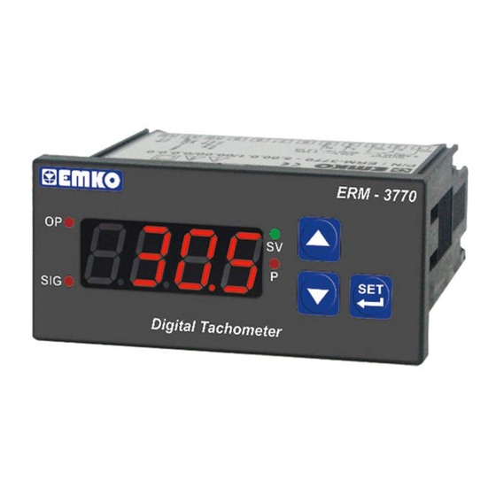
ERM-3770 77 x 35 DIN Size
Digital Tachometer
- 4 Digits Display
- NPN or PNP input type
- Working with Process Set and Alarm Set value
- Alarm output
Relay or SSR driver output (It must be determined in order.)
- Alarm Set value boundary
- Adjustable decimal point
- Division rate
- 0,07Hz to 10000Hz input signal
- Automatic sampling (1 sec. to 16 sec.)
- Programming mode password protection
Instruction Manual. ENG ERM-3770 02 V04 09/14
Advertisement
Table of Contents

Related Manuals for EMKO ERM-3770


Summary of Contents for EMKO ERM-3770
- Page 1 Relay or SSR driver output (It must be determined in order.) - Alarm Set value boundary - Adjustable decimal point - Division rate - 0,07Hz to 10000Hz input signal - Automatic sampling (1 sec. to 16 sec.) - Programming mode password protection Instruction Manual. ENG ERM-3770 02 V04 09/14...
- Page 2 ABOUT INSTRUCTION MANUAL Instruction manual of ERM-3770 Digital Tachometer consists of two main sections. Explanation of these sections are below. Also, there are other sections which include order information and technical specifications of the device. All titles and page numbers in instruction manual are in “...
-
Page 3: Table Of Contents
1.3 WARRANTY 1.4 MAINTENANCE 2. INSTALLATION........................... Page 2.1 GENERAL DESCRIPTION 2.2 FRONT VIEW AND DIMENSIONS OF ERM-3770 DIGITAL TACHOMETER WITH ALARM OUTPUT 2.3 FRONT VIEW AND DIMENSIONS OF ERM-3770 DIGITAL TACHOMETER WITHOUT ALARM OUTPUT 2.4 PANEL CUT-OUT 2.5 ENVIRONMENTAL RATINGS 2.6 PANEL MOUNTING... - Page 4 EU DECLARATION OF CONFORMITY Manufacturer Company Name Emko Elektronik A.S. Manufacturer Company Address: DOSAB, Karanfil Sokak, No:6, 16369 Bursa, Turkiye The manufacturer hereby declares that the product conforms to the following standards and conditions. Product Name : Digital Tachometer Model Number...
-
Page 5: Preface
1.Preface ERM-3770 series Digital Tachometers are design for measuring the period in Industry. They can be used in many applications with their easy use, alarm output, universal process input properties. You can easily adapt them to automation systems and mechanical process. -
Page 6: Ordering Information
Þ 1.3 Warranty EMKO Elektronik warrants that the equipment delivered is free from defects in material and workmanship. This warranty is provided for a period of two years. The warranty period starts from the delivery date. This warranty is in force if duty and responsibilities which are determined in warranty document and instruction manual performs by the customer completely. -
Page 7: Installation
2.Installation Before beginning installation of this product, please read the instruction manual and warnings below carefully. In package , - One piece unit - Two pieces mounting clamps - One piece instruction manual A visual inspection of this product for possible damage occured during shipment is recommended before installation. -
Page 8: General Description
Mounting Clamp Front Panel IP65 protection NEMA 4X Panel surface (maximum thickness 15 mm / 0.59 inch) 2.2 Front View and Dimensions of ERM-3770 Digital Tachometer With Alarm Output Maximum 15 mm / 0.59 inch ERM - 3770 Digital Tachometer 77 mm / 3.03 inch... -
Page 9: Front View And Dimensions Of Erm-3770 Digital Tachometer Without Alarm Output
2.3 Front View and Dimensions of ERM-3770 Digital Tachometer Without Alarm Output Maximum 15 mm / 0.59 inch ERM - 3770 Digital Tachometer 77 mm / 3.03 inch 4 mm / 0.16 inch 58.5 mm / 2.30 inch 2.4 Panel Cut-Out 110 mm / 4.33 inch (min) -
Page 10: Environmental Ratings
2.5 Environmental Ratings Operating Conditions Operating Temperature 0 to 50 °C Max. Operating Humidity : Rh (non-condensing) Altitude Up to 2000 m. Forbidden Conditions: Corrosive atmosphere Explosive atmosphere Home applications (The unit is only for industrial applications) 2.6 Panel Mounting 1-Before mounting the device in your panel, make sure that the cut-out is the right size. -
Page 11: Installation Fixing Clamp
2.7 Installation Fixing Clamp The unit is designed for panel mounting. 1-Insert the unit in the panel cut-out from the front side. 2- Insert the mounting clamps to the fixing sockets that located left and right sides of device and make the unit completely immobile within the panel Montage of the unit to a system must be done with it’s own fixing clamps. -
Page 12: Electrical Wiring
3.Electrical Wiring You must ensure that the device is correctly configured for your application. Incorrect configuration could result in damage to the process being controlled, and/or personal injury. It is your responsibility, as the installer, to ensure that the configuration is correct. Device parameters has factory default values. -
Page 13: Electrical Wiring Diagram
3.2 Electrical Wiring Diagram Electrical wiring of the device must be the same as ‘Electrical Wiring Diagram’ below to prevent damage to the process being controlled and personnel injury. P/N : ERM-3 OUTPUT 5A@250V V (+) (-) SSR Output 0 V Z NOTE-1 Relay or SSR Sensor Supply Voltage... -
Page 14: View Of The Device Label
3.3 View of the Device Label Device Label for Universal Process Input, 230 V Supply Voltage Input and Relay Output P/N : ERM-3770 - 5.00.0.1/00.00/0.0.0.0 OUTPUT 230 V ± 15% 5 A@250 V V 50/60 Hz - 1.5 VA 9 10 11 12... -
Page 15: Supply Voltage Input Connection Of The Device
3.4 Supply Voltage Input Connection of the Device Power Supply Input Connection External Note-1 Fuse (1 A T) Power Supply Switch Supply Voltage 230 V (± %15) 50/60 Hz or 115 V (± %15) 50/60 Hz or 24 V (± %15) 50/60 Hz or 24 V ( -%15 ;... -
Page 16: Process Input Connection
3.5 Process Input Connection 3.5.1 Proximity Connection PNP type operation NPN type operation PROX. PROX. 3.5.2 Switch Connection PNP type operation NPN type operation Z ± Sensor Supply Voltage is 12 V %35 maximum 30 mA. - Page 17 3.6 Galvanic Isolation Test Values of ERM-3 0 Digital Tachometer 2000 ERM-3770 ( for ERM-377 .3 ) Power Supply Ground 2000V V 2000V V Alarm Output Relay Output 2000V V Alarm Output SSR Driver Output 2000V V Process Input 2000V V...
-
Page 18: Alarm Output Connections
3.7 Alarm Output Connections 3.7.1 Relay Output Connection Device T Fuse Load Fuses must be selected according to the application. 3.7.2 SSR Driver Output Connection Device Last Control Element (SSR) Max.15 V Max.28 mA Fuse Load Fuses must be selected according to the application. -
Page 19: Front Panel Definition And Accessing To The Menus
4. Front Panel Definition and Accessing to the Menus 4.1 Front Panel Definition of ERM-3770 Digital Tachometer With Alarm Output Led Indication of Process Set Value Led Indication of Programming Changing Mode is Active Mode is Active Note-1 It is used to increase the... -
Page 20: Observation Of The Software Revision On The Display
4.3 Observation of Software Revision on the Display When power is first applied to the digital process indicator, software revision number is shown on the display. ERM - 3770 Software “rv” Revision Þ Digital Tachometer revision number ERM - 3770 Digital Tachometer Main Operation Screen is shown 4.4 Changing and Saving Process Set Value... -
Page 21: Programming Mode Parameter List
Division Rate Parameter ( Default = 60 ) It can be adjusted from 1 to 999. Pulse that is applied to the process input of ERM-3770 Digital Tachometer unit is shown according to this parameter. Revolution Per Minute is shown on the screen by dividing with this parameter value. - Page 22 Alarm Operation type Selection Parameter ( Default = 0 ) The unit starts to control the alarm output, when the power on. The unit starts to control the alarm output at the end of the Parameter value. After the power on and if alarm condition does not seem any more, the unit starts to control the alarm output.
-
Page 23: Operation Graphics Of Alarm Output And Alarm Types
4.6 Operation Graphics of Alarm Output and Alarm Types ( Alarm latching output is selected ) Power Power Time Time Alarm Alarm Status Status Time Time Decrement Alarm Alarm button must be pressed to make Output Output alarm output Active Active is passive Time... - Page 24 Deviation High Alarm Alarm Output Process Value Deviation Low Alarm Alarm Output Process Value Deviation Band Alarm Alarm Output Process Value Deviation Range Alarm Alarm Output Process Value = Process Set Value...
-
Page 25: Device With Alarm Output
4.7 Easy Access Diagram For Program Parameters 4.7.1 Device With Alarm Output 5 sec Password Entering Main operation screen Programming Mode Entering Screen Screen Enter the password with Increment and Decrement Buttons. Input Type Selection Password Entering Confirm the password Division rate Screen with SET/OK Button... -
Page 26: Device Without Alarm Output
4.7.2 Device Without Alarm Output 5 sec Password Entering Main Operation Screen Programming Mode Entering Screen Screen Enter the password with Increment and Decrement Buttons. Password Entering Input Type Selection Confirm the password Division rate Screen with SET/OK Button Decimal Point Program Mode Position Accessing Password... -
Page 27: Entering To The Programming Mode, Changing And Saving Parameters
4.8 Entering to the Programming Mode, Changing and Saving Parameters Main Operation Screen Note-1: If When Set/OK is pressed for 5 Programming Mode Programming Mode Entering Screen sec. “P” led starts flashing. If Access password is 0, Programming Mode accessing Press Increment then Programming password is defined, then... - Page 28 Programming Screen Input Type Selection Input Type Selection Value Parameter Press increment button for accessing to the Change the value with increment parameter value. Press Set/OK button for and decrement buttons. accessing to the next parameter. Programming Screen Input Type Selection Value Input Type Selection Parameter Press Set/OK button for...
- Page 29 5. Failure Messages on ERM- 3770 Digital Tachometer ERM - 3770 If the input frequency is lower than 0,07 Hz, then this screen will appear. Digital Tachometer ERM - 3770 If the input frequency is higher than 10000 Hz, then this screen will appear. Digital Tachometer ERM - 3770 If the Process Value is lower than 1, then this...
-
Page 30: Specifications
Emko Elektronik Sanayi ve Ticaret A.Þ. Demirtaþ Organize Sanayi Bölgesi Karanfil Sk. No:6 16369 BURSA/TURKEY Phone : +90 224 261 1900 Fax : +90 224 261 1912 Thank you very much for your preference to use Emko Elektronik Products. Your Technology Partner www.emkoelektronik.com.tr...
Need help?
Do you have a question about the ERM-3770 and is the answer not in the manual?
Questions and answers