Advertisement
Quick Links
Installation and Maintenance Instructions for
Cabin Units Type RS35X-CX0-E for CCS MicroVent System
1. Application
2. Handling
2.1 Marking
2.2 Weight
2.3 Transport
3. Storage
4. Installation
5. Duct connections
6. Electric connection
7. Wiring diagram
8. Thermostat
9. Regulation
10. Parts included
11. Maintenance
1.
Application
Cabin units from Novenco are used
for
heating,
distribution
discharge of air from high-pressure
air handling units to rooms and
cabins on ships, oil platforms etc.
2.
Handling
2.1 Marking
All cabin units are marked with
standard plates (figure 1). The plates
provide the name and address of
Novenco as well as the product type
and serial number, e.g. RS35X. The
serial number is unique for each unit.
In addition, the maximum power
consumption is also written on the
plates. The control boxes (CCU) are
also marked with plates showing type,
ID and serial number.
Figure 1
2.2 Weight
On
request
from
the
customer
Novenco can add the weights of the
cabin units to the marking of the
units.
Type
Weight [kg]
Dim. (HxWxL) [mm]
RS 35X
16.5
600x450x175
Diffuser
1.5
425x425x90
Total
18.0
——
Table 1
2.3 Transport
Cabin units from Novenco are packed
and delivered on pallets to allow
MU 14633 1212
No. 1 standard building, District 2, Period 3, Wangzhuang Industrical Center, New District,
fork-lift transport.
3.
Storage
The cabin units must be stored in a
dry place and at temperatures not
exceeding 45
C. Furthermore, it is
o
recommended to avoid long time
storage of the units in humid air
conditions (60% RH or more). This is
because of
risk
electrical
components,
unprotected against rust.
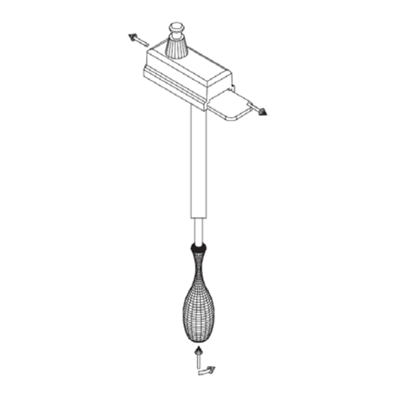
4.
Installation
The cabin units are available for
ceiling suspension (figure 2). Units are
delivered
with
and
brackets (A) incl. supply parts (B) for
fastening to the ceiling and sides of
the units.
Figure 2
It is important that the cabin units are
fastened to prevent sound nuisances,
caused by vibration.
5.
Duct connections
The cabin units are designed for
connection to large duct systems on
e.g. ships. Connect the cabin units to
the systems using insulated flexible
hoses and clamping rings.
It is important that the flexible hose is
straightened out and that the length
does not exceed 300 mm (figure 3).
Figure 3
Wuxi City, Jiangsu Province 214028, P.R.China
Tel: +86 510 8534 6622 Fax: +86 510 8534 6633
NOVENCO HI-PRES Air Handling Equipment (Wuxi) Co., Ltd
www.novenco-marine.com
6.
Power to the unit is supplied by
connecting 230V power cables to the
terminals L, N and PE as shown in the
wiring diagram. Refer also to the
electric diagram placed on the inside
of the lid of the terminal boxes.
Cables must be fastened by cable
to the internal
glands before feeding the Cabin units.
which
are
For room thermostat, its cable must be
tied up and fixed. Refer to the wiring
diagrams for correct connection of
cables.
The required output from the heating
four
suspension
elements is selected on the three
toggle switch (400, 800 and 1200 W) in
the outflow connection of the cabin
units.
7.
See figure 4 on page 3.
8.
The cabin units are equipped with
both the temperature sensors and the
mechanical
overheating protection. The sensor
has a programmed reset function
while the mechanical thermostat has a
manual reset function.
The sensor will switch off the heating
and
temperature within the cabin unit
exceeds 70
heating
sufficiently off.
Figure 5
If the sensor fails, the mechanical
thermostat will switch off the heating,
when the temperature exceeds 110
To re-activate the heating elements,
switch off the current to the cabin unit
in the fuse box. Remove the bottom
part of the diffuser by gently pulling
in the corners of the part. The manual
thermostat can then be accessed and
the small pin on the thermostat
GB
Electric connection
Wiring diagram
Thermostat
thermostats
for
alarm
will
on,
when
the
C, and back on when the
o
elements
have
cooled
C.
o
1 / 3
Advertisement

Related Manuals for NOVENCO RS35x-CX0-E series


Summary of Contents for NOVENCO RS35x-CX0-E series
-
Page 1: Wiring Diagram
MU 14633 1212 No. 1 standard building, District 2, Period 3, Wangzhuang Industrical Center, New District, Wuxi City, Jiangsu Province 214028, P.R.China Tel: +86 510 8534 6622 Fax: +86 510 8534 6633 NOVENCO HI-PRES Air Handling Equipment (Wuxi) Co., Ltd www.novenco-marine.com... -
Page 2: Parts Included
2 / 3 No. 1 standard building, District 2, Period 3, Wangzhuang Industrical Center, New District, Wuxi City, Jiangsu Province 214028, P.R.China Tel: +86 510 8534 6622 Fax: +86 510 8534 6633 NOVENCO HI-PRES Air Handling Equipment (Wuxi) Co., Ltd www.novenco-marine.com... - Page 3 3 / 3 No. 1 standard building, District 2, Period 3, Wangzhuang Industrical Center, New District, Wuxi City, Jiangsu Province 214028, P.R.China Tel: +86 510 8534 6622 Fax: +86 510 8534 6633 NOVENCO HI-PRES Air Handling Equipment (Wuxi) Co., Ltd www.novenco-marine.com...
Need help?
Do you have a question about the RS35x-CX0-E series and is the answer not in the manual?
Questions and answers