Table of Contents
Advertisement
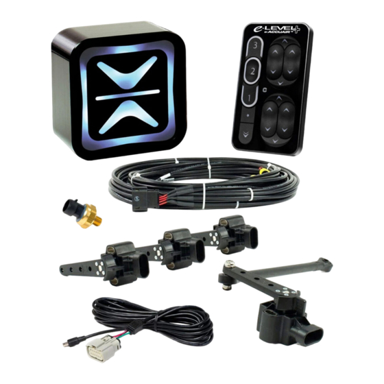
Thank you for purchasing the revolutionary e-Level™ system by AccuAir.
This system manages the height of up to 4 Air Springs and offers never
before seen accuracy in all applications by constantly learning your vehicle's
characteristics. Through the use of advanced height monitoring techniques,
this system automatically corrects for changes in load, whether driving or
parked, minimizing user input and maximizing accuracy throughout your
driving experience. To enhance the entire system's performance and reli-
ability, the AccuAir e-Level™ also manages your Air Compressor(s) to keep
onboard air at an ideal pressure for your application.
To maximize functionality, the AccuAir e-Level™ allows you to select from
three distinct vehicle heights through a Rocker Switch:
1.) Ride Height (The height that you will typically drive your vehicle at).
2.) Low/Cruise (Typically set at 10% of your total suspension travel).
3.) High/Extra Clearance (Typically set at 90% of your total suspension
travel to increase mobility and clear driving obstacles).
Installation Manual
ACCUAIR: Rocker Switch
Congratulations!
THE SYSTEM
MUST BE
CALIBRATED
BEFORE USE
SEE Opp Man
PAGE 6.
Advertisement
Table of Contents

Related Manuals for AccuAir e-Level

Summary of Contents for AccuAir e-Level
- Page 1 To enhance the entire system’s performance and reli- ability, the AccuAir e-Level™ also manages your Air Compressor(s) to keep onboard air at an ideal pressure for your application. To maximize functionality, the AccuAir e-Level™ allows you to select from three distinct vehicle heights through a Rocker Switch: 1.) Ride Height (The height that you will typically drive your vehicle at).
-
Page 2: Table Of Contents
Table Of Contents Description Page Number Terms & Conditions Wiring Diagram Installation Overview Mounting & Wiring Instructions 7-12 Testing Mechanical & Electrical Hookup Ride Height Sensor Installation 14-20 Setup Programming Mounting Templates 22-26... -
Page 3: Terms & Conditions
CUSTOMER. Warranty ACCUAIR will repair or replace any failed components for the life of the vehicle given that the components were installed and operated as intended by ACCUAIR. Upon the return of a failed component(s), ACCUAIR will determine the cause of failure. - Page 4 - Page 17 - - Page 17 - - Page 3 - - Page 5 - - Page 5 - AccuAir Rocker Switch Manual V2.7 © 2007 AccuAir Control Systems, L.L.C. AccuAir Rocker Switch Manual V2.7 © 2007 AccuAir Control Systems, L.L.C.
-
Page 5: Installation Overview
Test Wiring and Mechanical Components Install Ride Height Sensors CALIBRATE SYSTEM WARNING: Make sure to disconnect the vehicle battery ground terminal throughout the wiring process. - Page 6 - AccuAir Rocker Switch Manual V2.7 © 2007 AccuAir Control Systems, L.L.C. - Page 6 White/Orange 3.) Up 2 White/Purple 4.) Up 1 White 5.) Down 4 White/Gray 6.) Down 3 White/Green 7.) Down 2 White/Brown 8.) Down 1 White/Blue - Page 7 - AccuAir Rocker Switch Manual V2.7 © 2007 AccuAir Control Systems, L.L.C.
-
Page 7: Ecu Mounting
4.) Drill holes with a 3/16” drill bit and bolt the ECU down with the included #10-32 Allen head cap screws. For optional mounting, remove back tabs with diagonal cutters and a file. - Page 8 - AccuAir Rocker Switch Manual V2.7 © 2007 AccuAir Control Systems, L.L.C. - Page 8 Pressure Sensor Mounting. (In the top of the tank) Air Tank WARNING: e-Level™ System is NOT compatible with any other Pressure Sensor or Switch. Step-By-Step 1.) Coat the threads of the Sensor and any threaded fitting or adapter used in the air supply system with a thread sealer to help prevent air leaks.
- Page 9 5.) Install the Compressor Relay inline with the Compressor’s power line. 6.) Install the Ground Wire to vehicle/chassis ground. (Make sure to remove any rust or paint to ensure a thorough ground) - Page 10 - AccuAir Rocker Switch Manual V2.7 © 2007 AccuAir Control Systems, L.L.C.
- Page 10 6.) Route the single red wire labeled “BATT_12V” with a 10 Amp fuse to the vehicle battery. 7.) Mount the single black wire labeled “EC_GND” with the VU4 ground. - Page 11 - AccuAir Rocker Switch Manual V2.7 © 2007 AccuAir Control Systems, L.L.C.
- Page 11 Mounting Panel Mounting Panel Now connect the Orange wire labeled “ ” IGN_12V to a 12 Volt Vehicle Ignition Source. - Page 12 - AccuAir Rocker Switch Manual V2.7 © 2007 AccuAir Control Systems, L.L.C.
- Page 12 To fix any air leaks first lower the Air Springs “ ”, then turn the ignition OFF and depressurize the Air Storage Tank(s). - Page 13 - AccuAir Rocker Switch Manual V2.7 © 2007 AccuAir Control Systems, L.L.C.
- Page 13 If you mount a sensor too far out on an arm, it will travel too far and damage the sensor. See the following diagram for an illustration of this theory: Pivot Point Rotation Small Vertical Travel Large Vertical Travel - Page 14 - AccuAir Rocker Switch Manual V2.7 © 2007 AccuAir Control Systems, L.L.C.
- Page 14 Height Sensor Installation: WARNING: Sensor travel is limited to 2.75”. Over extension or over compression will damage the sensor. 2.75” Under/Over Extension - Page 15 - AccuAir Rocker Switch Manual V2.7 © 2007 AccuAir Control Systems, L.L.C.
- Page 15 “X”. We will call this distance “B”. Calculate the sensor travel by subtract- ing B from A, (Sensor Travel = A-B). - Page 16 - AccuAir Rocker Switch Manual V2.7 © 2007 AccuAir Control Systems, L.L.C.
- Page 16 2.75” of sensor travel drill or weld to at- tach the supplied ball stud at this exact point. Mounting Ball Stud Surface 1” Stand-off Allen Bolt (Optional) Thin Washer - Page 17 - AccuAir Rocker Switch Manual V2.7 © 2007 AccuAir Control Systems, L.L.C.
- Page 17 Once established, trace the outline of the sensor to the frame. - Page 18 - AccuAir Rocker Switch Manual V2.7 © 2007 AccuAir Control Systems, L.L.C.
- Page 18 Step 11.) Now that the sensor is mount- ed, repeat Step 8 and Step 9 to make sure that the clearance is still equal. Adjust the linkage if necessary. - Page 19 - AccuAir Rocker Switch Manual V2.7 © 2007 AccuAir Control Systems, L.L.C.
- Page 19 Identify the number label on each sensor cable and route it to the correct corner of the car based on the system diagram in the front of this manual. SENS_# 2.75" - Page 20 - AccuAir Rocker Switch Manual V2.7 © 2007 AccuAir Control Systems, L.L.C.
-
Page 20: Setup Programming
THE SYSTEM MUST BE CALIBRATED BEFORE USE Setup Programming: SEE Opp Man PAGE 6. System Calibration Refer to your OPERATION MANUAL for the System Calibration Procedure. - Page 21 - AccuAir Rocker Switch Manual V2.7 © 2007 AccuAir Control Systems, L.L.C. -
Page 21: Mounting Templates
Mounting Templates: 2.45 Drill Size: 13/64” #6,#7,#8 VU4 (Valve Unit) Mounting Template. - Page 22 - AccuAir Rocker Switch Manual V2.7 © 2007 AccuAir Control Systems, L.L.C. - Page 22 Drill Size: 13/64” #6,#7,#8 1.50 Bottom ECU Mounting Template. (Standard) Minimum leave clear space for connectors - Page 24 - AccuAir Rocker Switch Manual V2.7 © 2007 AccuAir Control Systems, L.L.C.
- Page 23 2.02 1.01 Drill Size: 13/64” #6,#7,#8 Rear ECU Mounting Template. (Optional) - Page 26 - AccuAir Rocker Switch Manual V2.7 © 2007 AccuAir Control Systems, L.L.C.
- Page 24 To enhance the entire system’s performance and reli- ability, the AccuAir e-Level™ also manages your Air Compressor(s) to keep onboard air at an ideal pressure for your application. To maximize functionality, the AccuAir e-Level™ allows you to select from three distinct vehicle heights through a Rocker Switch: 1.) Ride Height (The height that you will typically drive your vehicle at).
- Page 25 CUSTOMER. Warranty ACCUAIR will repair or replace any failed components for the life of the vehicle given that the components were installed and operated as intended by ACCUAIR. Upon the return of a failed component(s), ACCUAIR will determine the cause of failure.
- Page 26 Service Disable: CAUTION: For all under vehicle maintenance, you must first disable the air system by removing the main system fuse located near the battery. General Understanding: For simplicity of use and understanding we refer to the four wheels of a vehicle by number.
- Page 27 THE SYSTEM MUST BE CALIBRATED General Operation: BEFORE USE SEE PAGE 6. Dump/Kneel While driving or parked, you may choose to Dump/Kneel the Air Springs to 10% of their total travel for loading, etc. Press the “ ” Button momentarily. ”...
- Page 28 Setup Programming: Automatic System Calibration: (Suggested) WARNING: Do NOT use this procedure for KELDERMAN Systems because suspension damage will occur. Use the procedure on the next page. Before the system will operate, it must be calibrated to learn the vehicle charac- teristics.
- Page 29 Setup Programming: Manual Range System Calibration (Alternative to Automatic Calibration): Maximum Height will be determined by you; instead of your mechanical suspension limits! This procedure should only be used on suspensions that are likely to over extend. Your system must be calibrated to learn your vehicle’s characteristics before the automatic leveling features can be used.
- Page 30 Setup Programming: Manually Raise/Lower: Manual Adjustment to a New Height: In order to save a New Favorite Ride Height, you must first manually adjust each Air Spring to the height that you wish to save using the procedure outlined below. Once you have achieved the desired height on all corners, see “Saving A New Ride Height”...
- Page 31 Setup Programming: Manually Raise/Lower, Cont.: To Adjust Air Spring # 3: Press the Program “ ” Button 5-Times; the “ ” Arrow will flash 3-Times per second. Program Button Then within 5 seconds press the “ ” Button to fill or the “ ”...
- Page 32 Setup Programming: Tank Pressure Mode: Your system was shipped with the Tank Pressure Mode set at 150 PSI. If you have High Pressure Compressor(s) you can change the Tank Pressure Mode to 175 PSI or 200 PSI using the following Procedure: NOTE: The new Tank Pressure setting will NOT take affect until the system is RE-CALLIBRATED using the procedure on page 6 or 7.
- Page 33 Setup Programming: Saving A New Dump/Kneel Height: Once you have manually adjusted each Air Springs to the height that you wish to save: Hold the Program “ ” Button for approximately 3 seconds until both the “ ” and “ ”...
- Page 34 Setup Programming: Turning Ride-Height-On-Start ON/OFF: Your system was shipped with Ride-Height- On-Start enabled (ON). You may wish to dis- able (OFF) or re-enable (ON) this feature. When this feature is ON, the system will automatically re-level the vehicle to Ride Height every time that the IGN is switched ON.
- Page 35 Setup Programming: Turning RideMonitor™ Mode ON/OFF: Your system was shipped with RideMonitor™ Mode enabled (ON). You may wish to disable (OFF) or re-enable (ON) this feature. When RideMonitor™ Mode is ON, the system will Monitor the vehicle’s height whenever the IGN is ON and make adjustments for changes in load when deemed necessary.
- Page 36 Setup Programming: RideMonitor™ Mode Accuracy Level: RideMonitor™ Mode Accuracy Level will determine the acceptable variation from saved height for your vehicle (in other words, the distance away from saved height that it will not make a correction for). If you decide that you would prefer that the system was more or less accurate, you can use the procedure on the following page to either increase the accuracy by 8% (Level 3), or decrease the accuracy by 15% (Level 1).
- Page 37 Setup Programming: Adjusting Active Accuracy Level: LEVEL 1 = Lower Accuracy & Fewest Adjustments: Hold the Program “ ” Button for approximately 3 seconds until both the “ ” and “ ” Arrows flash; then Press the “ ” Button 1-Time to set to Active Level 1.
- Page 38 Operation Trouble Indication/Diagnosis: In the unlikely case of a system component failure during operation, both the “ ” and “ ” Arrows will flash simultaneously and sequentially to indicate the potential failures outlined below. NOTE: This is the ONLY time that both the “ ”...
- Page 39 Operation Trouble Indication/Diagnosis: Warning Indication: Diagnosis: Possible Cause: Ride Height Sensor Warning Flashes 1-time Ride Height Sensor #1 is not Verify wiring to Ride per second reading. Height Sensor #1. Stays On Check Ride Height Sensor #1 for failure. Flashes 2-times Ride Height Sensor #2 is not Verify wiring to Ride per second...
- Page 40 Position Select Switch Program TouchPad™ Button Controller IGN_12V (Main) 70Amp Fuse 12 V Batt (F1) 10 Amp ECU Fuse BATT_12V Compressor(s) (F2) 3 Amp Relay Compressor Relay Fuse When using other MFG’s COMP_1 valves: P_SENS Compressor 1 Compressor 2 (Optional) V_GND 1.) Up 4 White/Black...
Need help?
Do you have a question about the e-Level and is the answer not in the manual?
Questions and answers