Table of Contents
Advertisement
Quick Links
USER INSTRUCTIONS
TRIPOD SYSTEM
Complies with ANSI Z359.1, ANSI Z359.4 standards and OSHA 29 CFR 1910
and 1926 regulations.
Models: T100009, T210030B, T210060B, T210100B, T510000B, T510045,
T510000, T200001
Werner Co. Fall Protection
93 Werner Rd.
Greenville, PA 16125
FALL PROTECTION
724-588-2000
888-523-3371 toll free
888-456-8458 fax
Advertisement
Table of Contents

Related Manuals for Werner T100009

Summary of Contents for Werner T100009
- Page 1 FALL PROTECTION USER INSTRUCTIONS TRIPOD SYSTEM Complies with ANSI Z359.1, ANSI Z359.4 standards and OSHA 29 CFR 1910 and 1926 regulations. Models: T100009, T210030B, T210060B, T210100B, T510000B, T510045, T510000, T200001 Werner Co. Fall Protection 724-588-2000 93 Werner Rd. 888-523-3371 toll free...
- Page 2 Misuse or failure to follow these warnings and instructions may result in injury or even death. WORK SAFE! WORK SMART! IF YOU HAVE ANY QUESTIONS ABOUT THE PROPER USE OF THE EQUIPMENT, SEE YOUR SUPERVISOR, USER INSTRUCTIONS, OR CONTACT WERNER CO. FOR MORE INFORMATION. WARNING! WARNING! All components of the Tripod System must be inspected prior to each use in accordance with the requirements of OSHA 29 CFR 1910.140 and 1926.502.
-
Page 3: Use Instructions And Limitations
TRIPOD SYSTEM USER INSTRUCTIONS USE INSTRUCTIONS AND LIMITATIONS MPORTANT Before use, the user must read and understand these User Instructions. Keep these User Instructions for reference. URPOSE The Tripod System is designed to be used as part of a personal fall arrest, rescue, work positioning, or material handling system. - Page 4 “competent person” per OSHA 29 CFR 1926.503 or a "qualifi ed person" per OSHA 29 CFR 1910.30. 13. REPAIRS: Only Werner Co., or persons or entities authorized in writing by Werner Co., may make repairs or alterations to the equipment.
-
Page 5: Connection Requirements
TRIPOD SYSTEM USER INSTRUCTIONS OSHA states: Anchorages used for attachment of personal fall arrest equipment shall be independent of any anchorage being used to support or suspend platforms and capable of supporting at least 5,000 pounds (22.2 kN) per employee attached, or shall be designed, installed, and used as part of a complete personal fall arrest system which maintains a safety factor of at least two;... - Page 6 specifi cally designed the snap hook to be used to connect to the equipment in question. The following connections must be avoided, because they can result in rollout* when a non locking snap hook is used: • Direct connection of a snap hook to horizontal lifeline. •...
-
Page 7: System Components
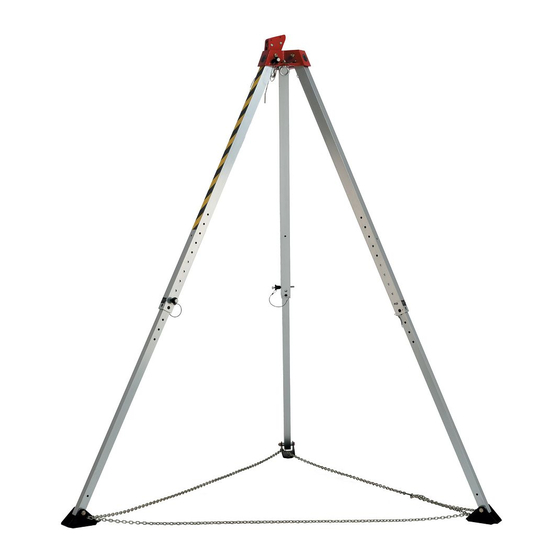
IMITATIONS All components and subsystems used with the Tripod System have been tested as part of a complete fall arrest system. Only components and subsystems approved by Werner Co. are to be used with the Tripod System. NCHORAGE ONNECTORS : T100009 RIPOD The high strength aluminum Tripod extends from 70 inches (1.7 m) to 84 inches... -
Page 8: Installation
ONNECTING EVICES ETRACTING IFELINE WITH ESCUE APABILITY T210030, T210060, T210100 The 3-Way Self Retracting Lifeline with Rescue Capability (SRL-R) are designed for a single user with a capacity up to 310 pounds (140 kg) including clothing, tools, etc, and comes in 30 feet (T210030), 60 feet (T210060) and 100 feet (T210100) lengths. - Page 9 TRIPOD SYSTEM USER INSTRUCTIONS ULTIPLE YSTEMS Multiple systems may be attached to the Tripod; however, the Tripod is for a single user only. A maximum of two systems may be attached to one Tripod, and a maximum of one system may be attached to any one Tripod leg. WARNING! The Tripod System is designed for up to two users at one time for emergency rescue applications only.
- Page 10 TTACH THE ATERIAL OIST The material hoist attaches to the mounting bracket with four bolts supplied with the mounting bracket. Insert the four bolts through the mounting bracket and into the material hoist. Tighten in a diagonal sequence using allen wrench. Place material hoist on the upper leg of the Tripod, orientated so the drum of the material hoist is towards the top of the Tripod.
- Page 11 TRIPOD SYSTEM USER INSTRUCTIONS • The 3-Way SRL-R may attach to a rescue yoke in rescue applications. The rescue yoke connects to Class E shoulder D-rings on the full body harness of a user in need of rescue. See full body harness user instructions for more information.
-
Page 12: Inspection And Maintenance
INSPECTION AND MAINTENANCE WARNING! If inspection reveals any defect, inadequate maintenance, or unsafe condition, remove from service until a “competent person” , as defi ned by OSHA 29 CFR 1926.32(f), can determine the need for authorized repair or disposal. CAUTION! Proper Personal Protective Equipment must be worn when performing Inspection and Maintenance procedures. -
Page 13: Cleaning And Storage
TRIPOD SYSTEM USER INSTRUCTIONS Each leg must be able to lock in place at the head of the Tripod with the locking pin. Each leg must be straight and able to lock into place with the locking pin when extended. The foot on each leg must pivot freely and have the rubber skid pads attached. - Page 14 P/N113194-03 Rev A 3/17 in injury or even death. Standards: ANSI Z359.1, ANSI Z359.4, OSHA 29 CFR 1910.140 and 1926.502 Werner Co. 113194-03 93 Werner Road, Greenville, PA 16125 1-888-523-3371 www.wernerco.com P/N113194-01 Rev A 3/17 MADE IN INDIA Page 14...
-
Page 15: Specification
TRIPOD SYSTEM USER INSTRUCTIONS EQUIPMENT RECORD MODEL NUMBER PURCHASE DATE SERIAL NUMBER ASSIGNED TO DATE MANUFACTURED SPECIFICATION ERNER RIPOD YSTEM This product meets ANSI Z359.1 and ANSI Z359.4 standards and OSHA 29 CFR 1910.140 and 1926.502 regulations for the anchorage connector component of a complete personal fall arrest/rescue system. - Page 16 Werner Co. Fall Protection 93 Werner Rd. Greenville, PA 16125 724-588-2000 • 888-523-3371 toll free • 888-456-8458 fax PN113190-01 ©2017 Werner Co. Rev A 3/17...
Need help?
Do you have a question about the T100009 and is the answer not in the manual?
Questions and answers