Advertisement
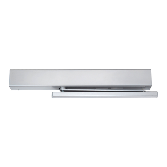
Double Egress Arm
and Slide Track
Hinge (pull) side of door mounting
Combination Door Closer-Holder and Releasing
Device With Integral Smoke Detector
All dimensions are in inches and (millimeters) unless otherwise noted.
RH - Right Hand Door
LHR - Left Hand Reverse
Smoke Detector Reset Button
Smoke Detector
Closer/Holder
Selective Hold Open
Cam & Switch
Assembly
Backplate
Mtg Screw (5)
Arm Screw
Track Mtg
Screw (3)
Cover
Requirements:
Units are handed. Hand of unit and hand of door must be the
same.
Door must be hung on butt hinges or ¾" (19) offset pivots.
Door thickness must be 1¾" (44) minimum 2¼" (64) maximum.
Door must swing freely through the entire opening and closing
cycle before beginning the installation procedure.
Frame face must be a minimum of 2" (51).
NOTE: For special applications a separate door and frame preparation template is packed with these
instructions. Use this instruction sheet for installation sequence and closer adjustments only.
For wiring, see "Wiring Instructions" part number
AN INCORRECTLY INSTALLED OR IMPROPERLY
ADJUSTED DOOR CLOSER CAN CAUSE
PROPERTY DAMAGE OR PERSONAL INJURY.
THESE INSTALLATION INSTRUCTIONS SHOULD
BE FOLLOWED TO AVOID THE POSSIBILITY OF
MISAPPLICATION OR MISADJUSTMENT.
Installation Instructions
80-9372-0095-015 (02-09)
Note:
Only for
hinge side
frame reveals
of 1/8" to 3"
(3mm to
76mm)
Backplate
Hook-up Board
Test Switch
Access Tube
Main Arm
Slide Track
Slide Assembly
Cover Mtg
Screw (3)
Concealed Wired Unit Shown
Selective Multipoint
Ceiling Line
Left Hand Door - LH
Right Hand Reverse - RHR
Preparation for Fasteners
Fasteners
1/4" - 20 machine
screw
Standard
Sleeve nuts and bolts
Optional Through-bolts and
grommet-nuts
Use of an auxiliary door stop, by
others, is required.
Ceiling clearance must be a minimum of 4" (102).
Power input to unit must be of the same voltage as that stated
on the unit.
Unit to be mounted on interior of building in dry environment,
maximum humidity of 95%.
See NFPA70 for wiring requirements and NFPA72 for alarm
system requirements.
80-9342-0902-015 (02-09)
Master Unit
Models
DE 6 PULL
Hold Open
4
Min
(102)
2
Min
(51)
Door or Frame
Drill-Sizes
Drill: #7 (0.201" dia.)
Metal
Tap: 1/4" - 20
Hollow
9/32" (7 mm) through;
Metal
3/8" (9.5 mm) door face
opposite to closer
Aluminum
3/8" (9.5 mm) through
or Wood
9/32" (7 mm);
3/8" (9.5 mm) dia. x
All
3/8" (9.5 mm) deep on
door opposite to closer
.
Advertisement
Table of Contents

Related Manuals for Rixson DE 6 PULL

Summary of Contents for Rixson DE 6 PULL
- Page 1 ADJUSTED DOOR CLOSER CAN CAUSE PROPERTY DAMAGE OR PERSONAL INJURY. Models THESE INSTALLATION INSTRUCTIONS SHOULD BE FOLLOWED TO AVOID THE POSSIBILITY OF MISAPPLICATION OR MISADJUSTMENT. DE 6 PULL Installation Instructions 80-9372-0095-015 (02-09) Selective Multipoint Double Egress Arm Hold Open and Slide Track...
- Page 2 Determine Hand Left Hand Door - LH RH - Right Hand Door Right Hand Reverse - RHR For Concealed Wire Only LHR - Left Hand Reverse 19-3/16 For Concealed (487) 11-3/8 8-11/16 Wiring Only (102) (289) (221) 1-1/16 3-1/4 1-3/8 (22) 4-1/8 (27)
- Page 3 START START ROTATE ROTATE HERE HERE TO HERE, TO HERE, THEN REMOVE THEN REMOVE RE-INSTALL Main Arm HERE RIGHT LEFT HAND HAND Arm Washer Arm Screw PINION FLAT Arm Stud Open Latch Slide and Sweep Assembly Valves with 1/8” wrench provided.
- Page 4 85° to 180°. The hold open starting point may be changed (increased or decreased) by loosening the selective hold open cam screw, rotating the cam to the desired new starting point and re-tightening the cam screw. Rixson ® is a registered trademark of Yale Security Inc., an ASSA ABLOY Group company. Copyright © 2009 Yale Security Inc., an ASSA ABLOY Group company.
Need help?
Do you have a question about the DE 6 PULL and is the answer not in the manual?
Questions and answers